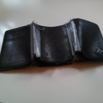
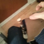
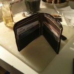
After 15 years of use and abuse in my sweaty jeans, my wallet had finally reached the end of its run. Looking at a worthy replacement, I started shopping around the web and found several canditates. However, either slightly too bulky or just out of my means, I finally decided to build my own. A tedious search on the web turned up this one, a template for a simple bifold wallet with slots for two cards on each size. Careful analysis of the design indicated that there was much more to leather work than met the eye and instead of cooking up my own design only to risk the wallet not folding properly, I opted to simply follow the instructions (for once). It’s sturdy, maintainable and looks good; hopefully, it will outlast me.
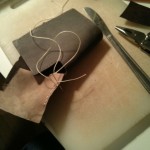
Wanting to offer some as Christmas gifts as well, I ended up making three. Here is abbreviated list of the challenges I encountered during the building:
leather is difficult to find, be thorough in you search for sources, call every fabric shop and cobbler in your region and once you find some, get there and feel the material for yourself;
sewing leather is long and tedious if you want to do it properly (with saddle stitching in this case), get the right needles and be patient, I ended up going through David Attenborough’s entire series on plants and birds in the course of putting mines together;
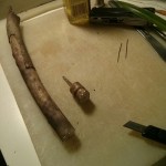
burnishing the edges of the leather (ie: make them smooth and shiny) is hard and appears to not work on vegetables tanned types; you also need a burnisher, which I build by cutting a section of a branch, hooking it up to a Dremel and then sculpting it to make a groove.
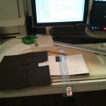
Having filled up the last page of my store bought dive log, I decided it was time I started printing my own log sheets. I wanted a template that could fit in a small binder (half letter (5.5″ x 8.5″) or A5), where there was enough space on the page to log two dives and that gave me ample space for comments while providing the standard diving data fields. Unfortunately, I could not find anything that suited my needs so I decided to put together my own.
The layout is compact and text has been kept to a minimum: you write the units yourself. Once it has been printed (on good paper stock and double side preferably), cut the sheets in half along the dotted line, punch holes if you want to store them in a binder and go log some dives.
For those interested in the source, here it is. Suggestions for improvements are welcome!
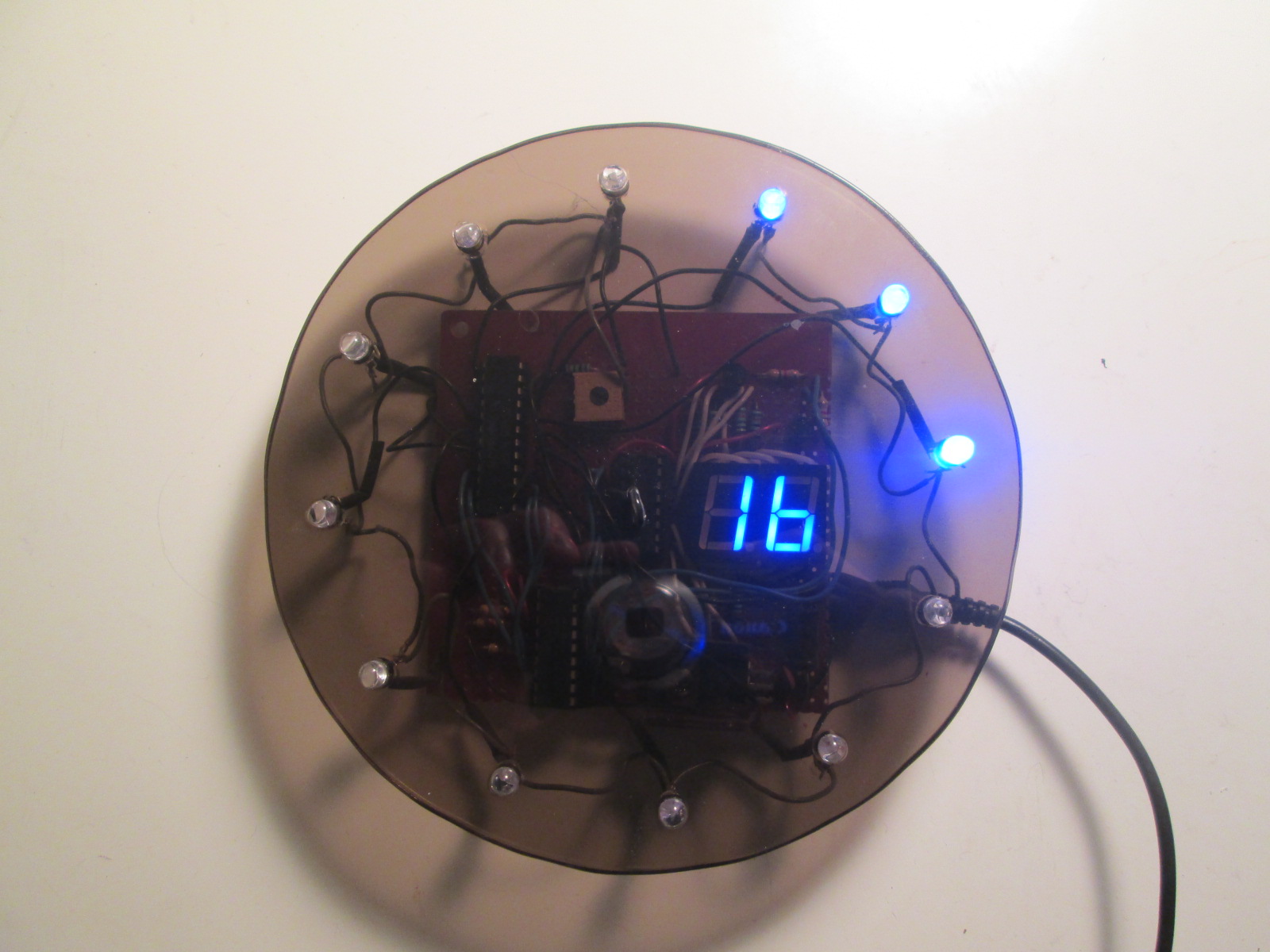
Going way back to 2006 actually, to my very first electronics project, a digital clock with an analog twist. I had very little experience in programming let alone electronics and back then, user-friendly prototyping platforms were not that common and mostly underground; the arduino had only came out the year before.
The clock with its faceplate removed
For many evenings in my dorm room I battled with a bunch of components and a serially programmed Microchip PIC16F628. I recall having loads of trouble getting inputs to the chip functioning, with the minutes and hours buttons activating or refusing to work with a mind of their own. The internet was not of much help but in the end I figured it out: pull-down resistors. No wonder I could not find anything on the subject, for someone with the least bit experience in electronics, it’s one of the most elementary concepts, akin to trying to troubleshoot a TV that’s not plugged in. For beginners attempting to learn electronics by themselves, its nothing but trivial.
Eventually, I succeeded in putting a working clock together on the breadboard that I had. Back in my basement over the next break from school, I soldered the whole thing on a perfboard and equipped the circuit with a face plate. The programming is rudimentary, the circuit is much less than optimal and in spite of the 32kHz watch crystal, there is still a bit of drifting but I could not have asked for a better learning experience. Some LEDs have burnout, but even after those years, it’s still doing a fine job at reminding me that time is ticking.
Note: this post about an electronics project has been sitting as a draft since 2011 so some of its content might appear outdated. Regardless, I’ve been using the device since then so I figured I should commit it to posterity.
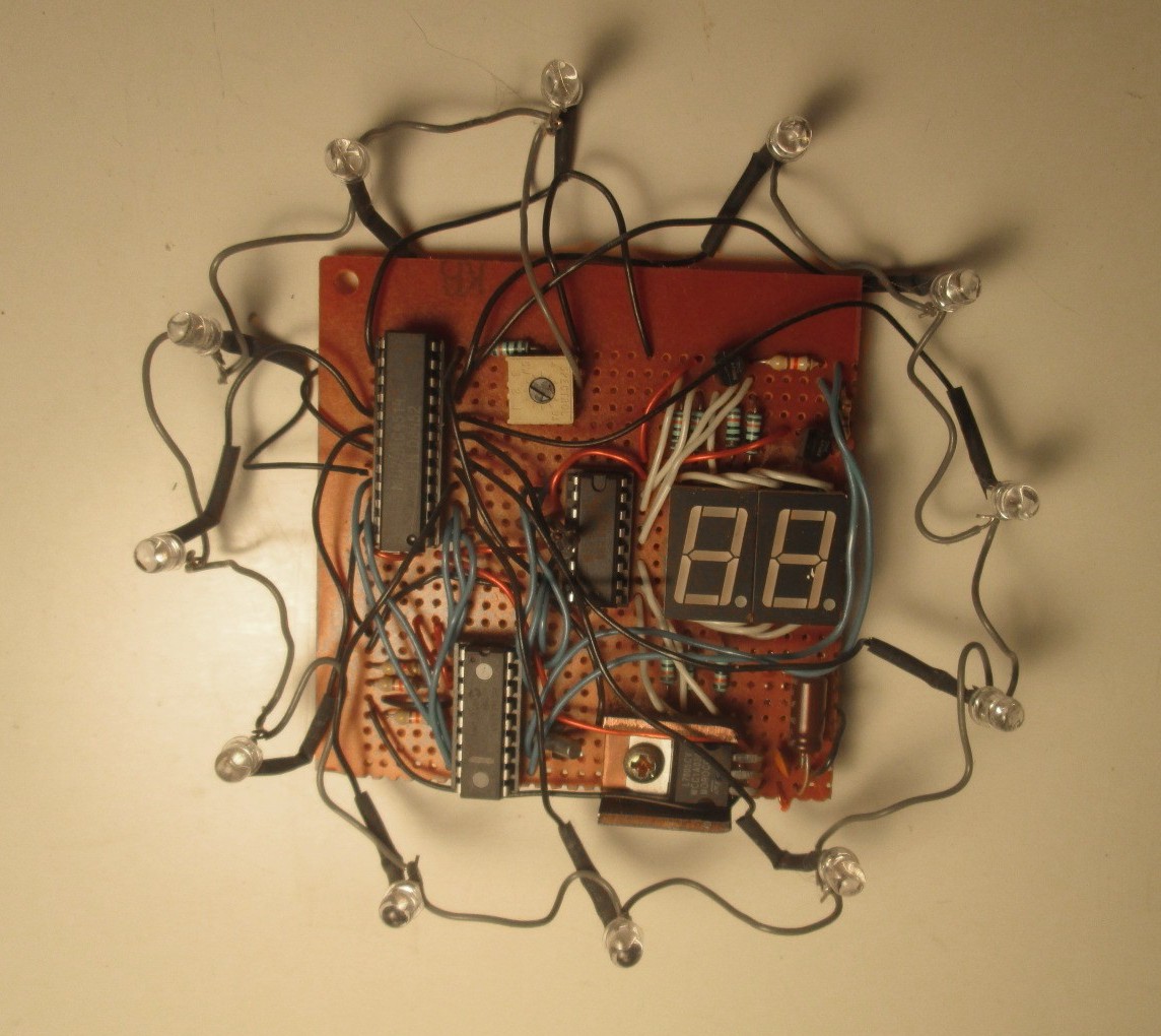
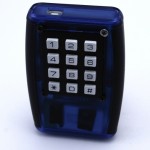
To my computer, its simply a USB keyboard, nothing less, but to me its a remote I can use on any platform with no line of sight. I decided to name it the keyMote. Sounds a bit odd to my ears but its a fitting name.
Here is how it works. There are two parts to this system, the remote, which is battery powered, and the base, which is hooked up to a computer. The remote is a simple keypad (In the case of the prototype, its a numeric keypad, but really, it could be any interface) with a transmitter hooked up to it. The base, the other end, is a receiver with USB Human interface device functionality, in other words, a vanilla USB keyboard. When a button is pressed, the remote sends the identifier of that button to the base which then looks up in a table the keystrokes this identifier is mapped to and sends those to the computer via USB. What button is mapped to what keystroke is entirely configurable using a serial terminal interface (shell) to the base. It can be anything, Ctrl-C, Alt-Shift-F, PageUp, etc. Getting it to interface with your program is then simply a matter of configuring keyboard shortcuts.
The use case
Here is the actual use case that spawned the idea. I was doing some plumbing work in my kitchen with the computer playing songs in the background. It then hit one in the playlist that I especially hate (but keep for nostalgia), but I was in no position to change it as it would have implied bending out of underneath my sink, walking to my computer and then hitting Ctrl + Shift + Right to skip to the next tune. I use Linux and at that time, the media buttons on my keyboard were not operational, I knew very few remotes would work on my platform and finally, I had no line of sight with the computer, so infrared was out of the question. Agreed, a wireless keyboard would have done the trick, but those tend to be limited in range, and well, they are still keyboards, so you have to do the key combinations yourself and are somewhat cumbersome to lug around. So I thought: Why not get something that will emulate my hands typing the keyboard shortcuts?
I looked around for possible off-the-shelf solutions, but none of them were well supported under Linux; basically they all required drivers and were proprietary and as we all know, anything with a driver is dependent on company support an will get dumped sooner of later. The keyboard idea was starting to get some traction. It was the obvious medium to go with, the USB human interface device standard has been around for a decade or so and will likely stick for a few more but more importantly, it is understood by most OSes. Failing to come across anything that would suit my purpose, I set out to develop one from scratch and after a bit of work (or a lot, depending where you come from), I had what I wanted: a simple, rugged self-contained system with no drivers attached, plenty of battery life and a way to make it type whatever I want. Currently, its mapped to my MP3 player, sound controls, Video player controls and some programming IDE functions. It could very well launch applications, toggle the visibility of certain windows (via the window manager), start scripts; it can do anything a keyboard can do.
The system
The main hardware components are an arduino, a wireless receiver and transmitter pair and another microcontroller hooked up to a battery in the remote. I started off with trying out wireless communication on the arduino IDE but soon converted to C/C++ for the added flexibility once I was past figuring out the libraries.
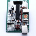
Base
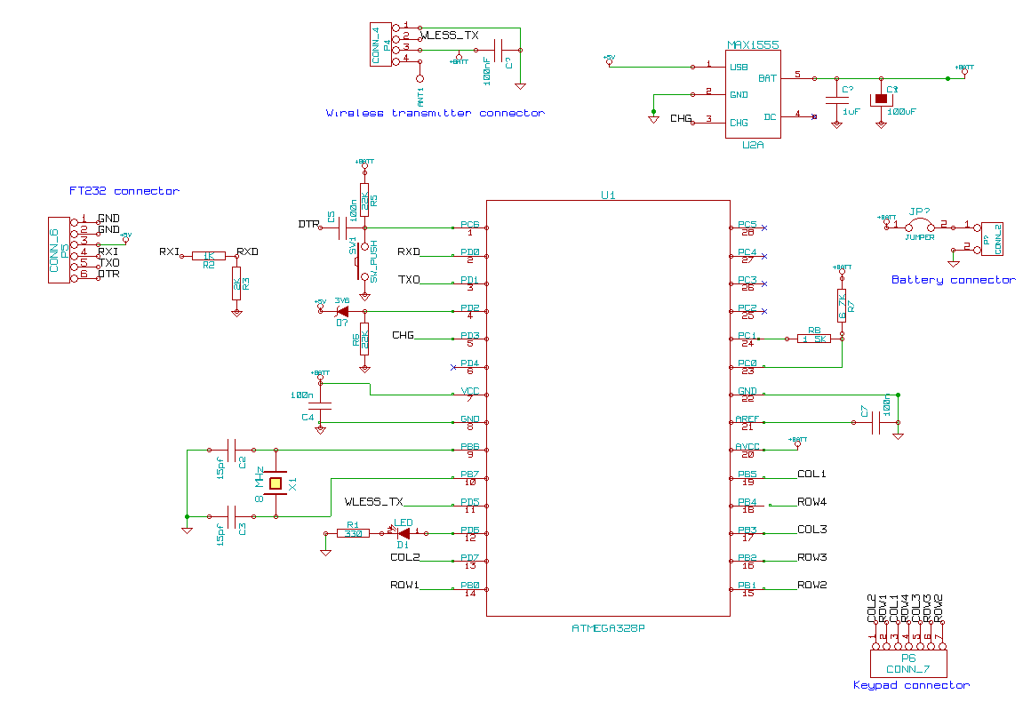
The base software is mainly an interface between two libraries, VirtualWire and V-USB along with a shell to configure the mapping between remote key codes and key strokes. VirtualWire is a library that makes exchanging bits (a lot harder than the datasheet implies, what you send on TX is quite what you get on RX) between vanilla wireless interfaces very straightforward. V-USB is a marvelous implementation of the USB protocol on the AVR using nothing but bit-banging. It’s quite limited in capacity but it’s extremely lean and makes USB accessible for anyone with the patience to understand the protocol. While the actual serial shell is a fair chunk of code, it is needed only for configuration, so this project is mainly composed of glue code and basic electronics. The arduino’s USB connector is used for serial shell functionality, where using commands it is possible to consult statistics about the system, get debugging data, but more importantly map key Ids to key strokes. The other USB connector is the actual keyboard.
The base schematic
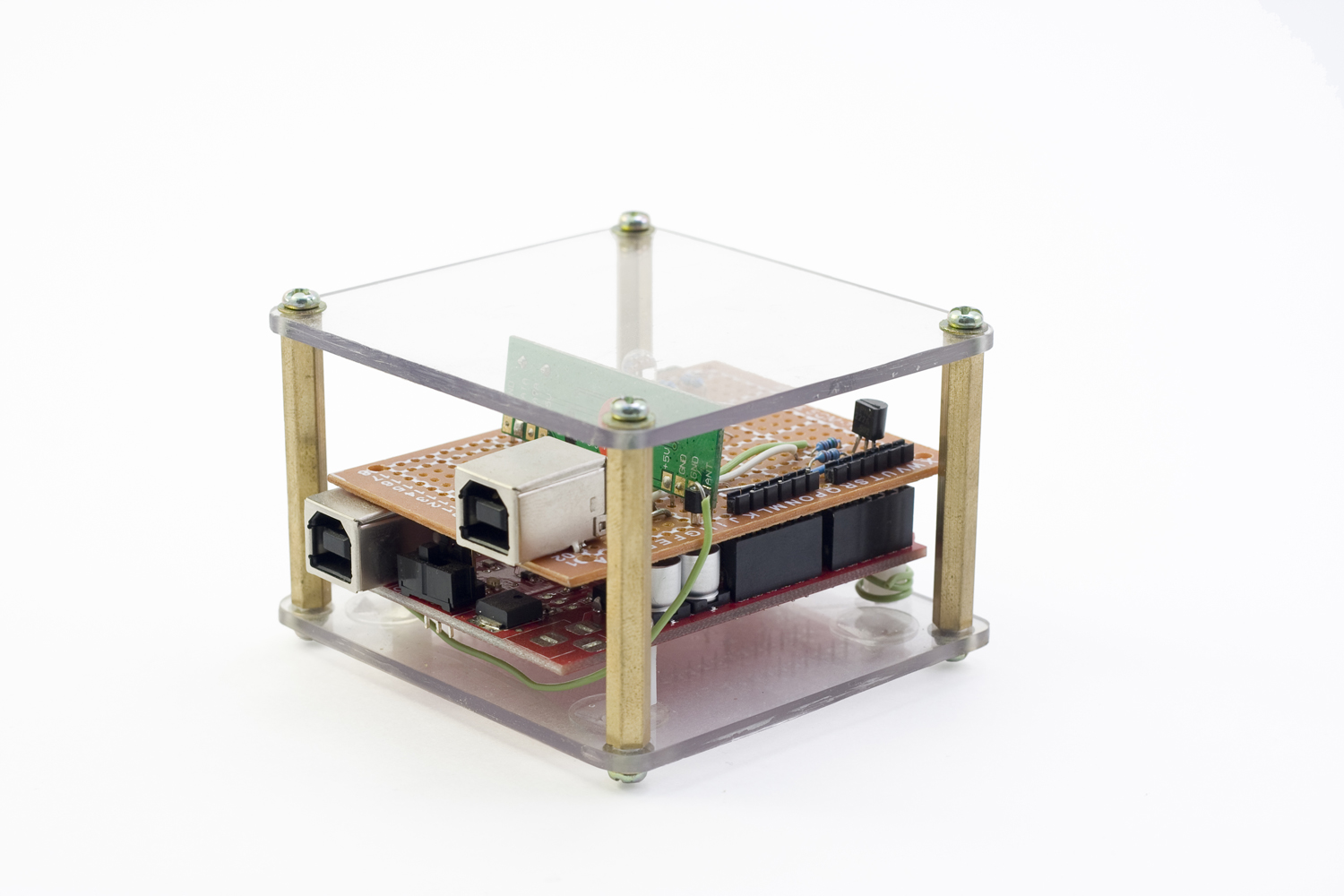
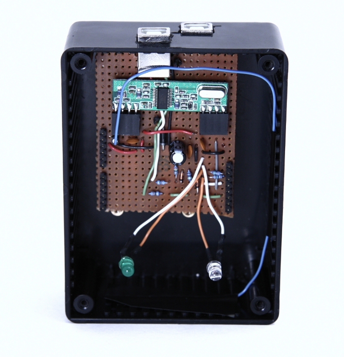
Since I had an arduino to spare, I decided to implement the USB and wireless interfaces as a shield rather than build a specific circuit. Really, the only hurdle was the weird spacing between pin 7 and 8 (why?), but that got solved by soldering angled headers to the side of the perfboard at an offset with the holes they would normally fit in. The wireless receiver was a breeze to connect but the USB interface was slightly more complex, with a couple of zener diodes and resistors to get the correct line levels.
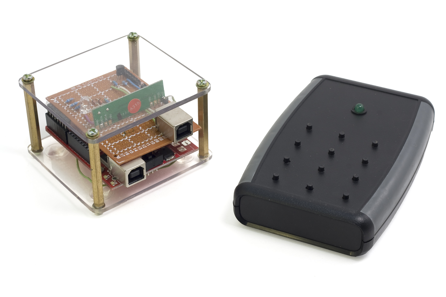
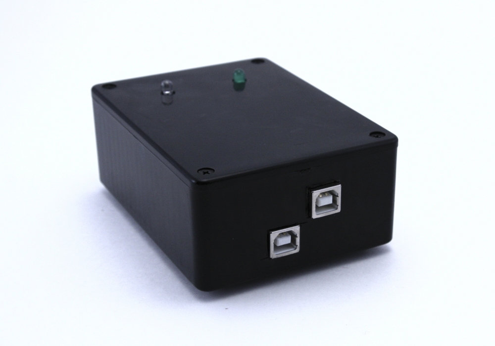
Two versions of the base were created but they only differ in the way they look.
Base version 2
Base version 1
Base version 1 opened
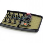
Remote
The base is mostly software but the remote is mostly electronics. The code is essentially a loop that intercepts keypad presses and sends them out through the transmitter to the base. Since it’s battery powered, the complexity of the firmware lays essentially in the power management code as the electronics cannot be left on running at full power all the time.
Remote prototype schematic
I built two different versions of the remote. The prototype which used another ATMega328P (same MCU as the arduino) featured an off-the-shelf keypad and a USB connector with a MAX 1555 for charging. The MCU is left in its deepest sleep mode all the time and is only waken up when a key press occurs. As a result, power consumption is in the order of nano amperes which yields a battery life of a couple months under normal usage when hooked up to a 900 mAh LiPo battery.
Remote version 2 schematic
The second version goes even further into increasing battery life. The ATMega328P, overkill for this application, is replaced with an ATTiny84 and the keypad interface is hooked up a circuit that turns on the micro controller and the transmitter from a fully off state only when a key is pressed. It’s using the same battery as the prototype but the power usage is so minute that after close to two years I have not yet exhausted the battery and measuring the drain is beyond my multimeter’s range. Granted, usage has been on and off due to me leaving for extended periods of time but still, that’s a pretty decent statisctic. So much so that I had plans to convert it to a solar cell and supercapacitor design but sadly, all my prototyping efforts led to failure.
Remote prototype
Internals of the remote prototype
Internals of the remote version 2
The result
It was quickly put together and yielded a result of fairly high quality and convenience for the effort. I’m not saying there is no room for improvement, but it was refreshing to do a project that was not plagued by unforeseen complexity and feature creep. I’ve been using both remotes for the past two years and have been getting months of battery life for the prototype and for its successor, well, it’s still running after two years. Range wise, I can send commands at a distance of about 10 meters through several walls so it more than sufficient.
Since I have no plans to revisit the project in the near future, I’m publishing the source code and the schematics (made with gEDA) up for download on a GNU GPL license. Take note that some of the third-party libraries use a different license which is specified in their respective folders. Should you have any questions, do not hesitate to reach me through the comments or the contact page.
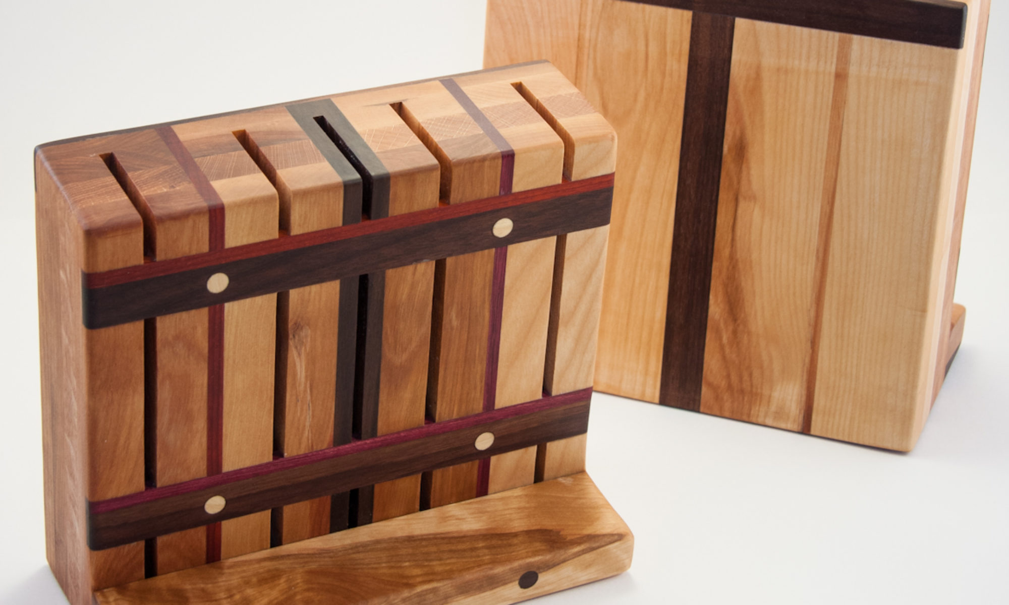
Last out of the workshop are four knife blocks made from cherry, oak (not obvious), walnut and two exotic flavours: padauk (red) and purpleheart (purple). To keep cost low, the large cherry/oak pieces were laminated from scraps bought for cheap at the lumber yard.
The design is somewhat unusual as the poor precision of my tools would not allow me to build a completely enclosed block like is most often seen. An added benefit however is that the slots are all of a similar size, so no need to look for the proper spot when dropping a knife in.