Your iPhone fell in the water and no longer works? Here’s how you might be able to fix it. My girlfriend had dropped her’s in the toilet (don’t ask how) and with a bit of patience and some chemicals I was able to get it working again. This little trick might also work with any other kind of electronics.
Take your phone apart completely. iFixit has some very well made guides for most iPhone models. (If you don’t have the proper screwdrivers, spudgers, suction cups and things, Ebay is a good place to get them, they only cost a couple of dollars.)
Take the logic board out.
Look for water deposits and corrosion (bluish/greenish spots) on the logic board and everywhere inside the phone.
Put that logic board and every other part that’s been exposed to water in a plastic container.
Pour a generous amount of isopropyl alcohol (the higher the concentration the best) in the container so that the parts are completely submerged.
Let them sit there for a couple of days, intermittently shaking the container to swoosh the alcohol around.
Get a soft bristled toothbrush, dunk it in the alcohol and gently brush off all the corrosion that you can see. Pay extra attention to the connectors and the logic board, inspect them meticulously and clean them thoroughly.
Let the parts dry for two or more days. (You can put the alcohol back in its bottle.)
Put the phone back together, working in reverse from the guide you used originally to take it apart.
Plug it in and hope for the best.
Hope this helps… If you have any other suggestions and if it worked with your model of phone or electronics, I’d appreciate it if you leave a comment.
Going way back to 2006 actually, to my very first electronics project, a digital clock with an analog twist. I had very little experience in programming let alone electronics and back then, user-friendly prototyping platforms were not that common and mostly underground; the arduino had only came out the year before.
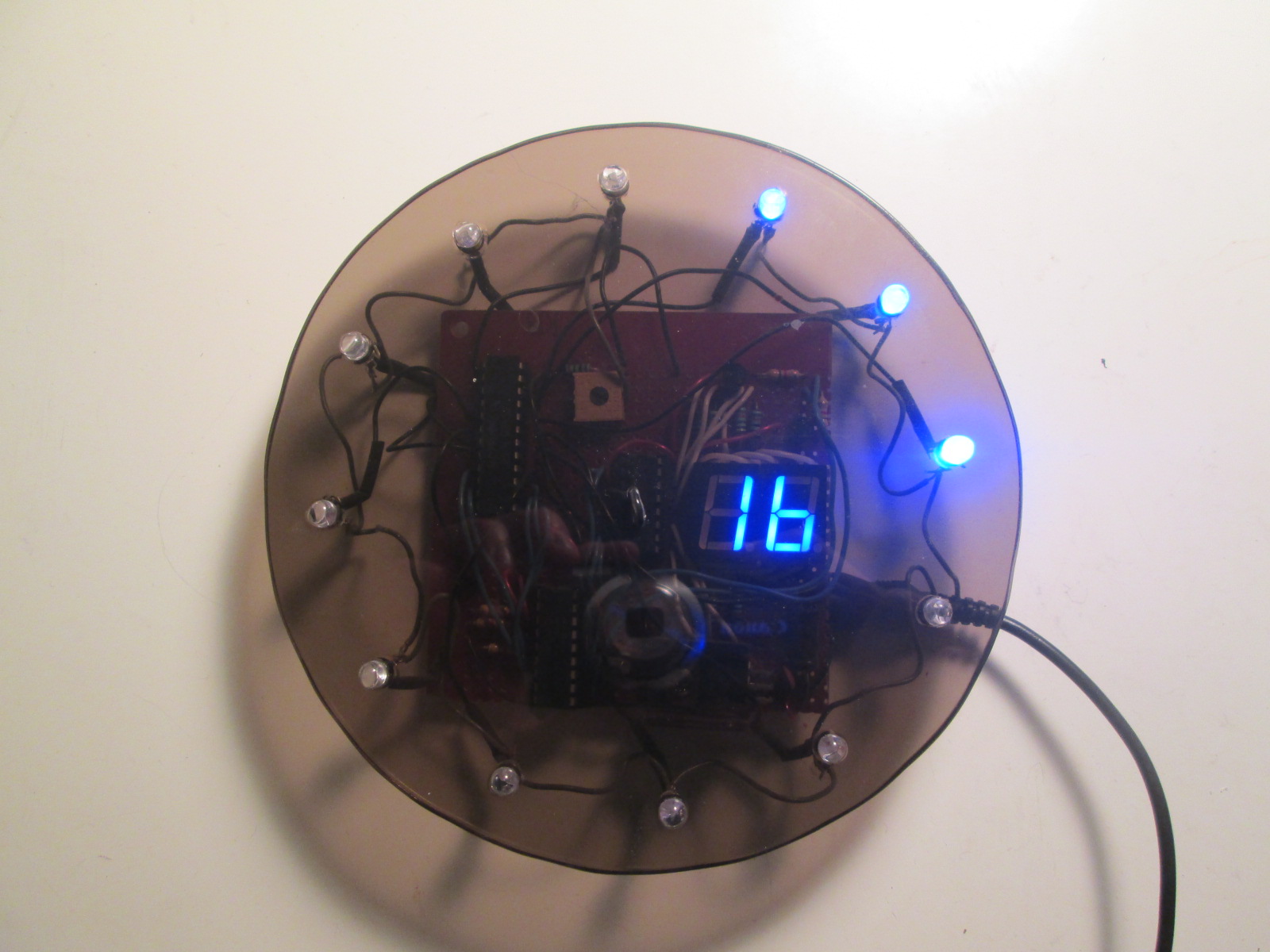
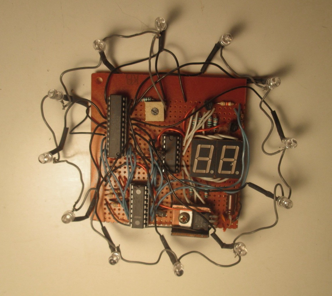
The clock with its faceplate removed
For many evenings in my dorm room I battled with a bunch of components and a serially programmed Microchip PIC16F628. I recall having loads of trouble getting inputs to the chip functioning, with the minutes and hours buttons activating or refusing to work with a mind of their own. The internet was not of much help but in the end I figured it out: pull-down resistors. No wonder I could not find anything on the subject, for someone with the least bit experience in electronics, it’s one of the most elementary concepts, akin to trying to troubleshoot a TV that’s not plugged in. For beginners attempting to learn electronics by themselves, its nothing but trivial.
Eventually, I succeeded in putting a working clock together on the breadboard that I had. Back in my basement over the next break from school, I soldered the whole thing on a perfboard and equipped the circuit with a face plate. The programming is rudimentary, the circuit is much less than optimal and in spite of the 32kHz watch crystal, there is still a bit of drifting but I could not have asked for a better learning experience. Some LEDs have burnout, but even after those years, it’s still doing a fine job at reminding me that time is ticking.
Note: this post about an electronics project has been sitting as a draft since 2011 so some of its content might appear outdated. Regardless, I’ve been using the device since then so I figured I should commit it to posterity.
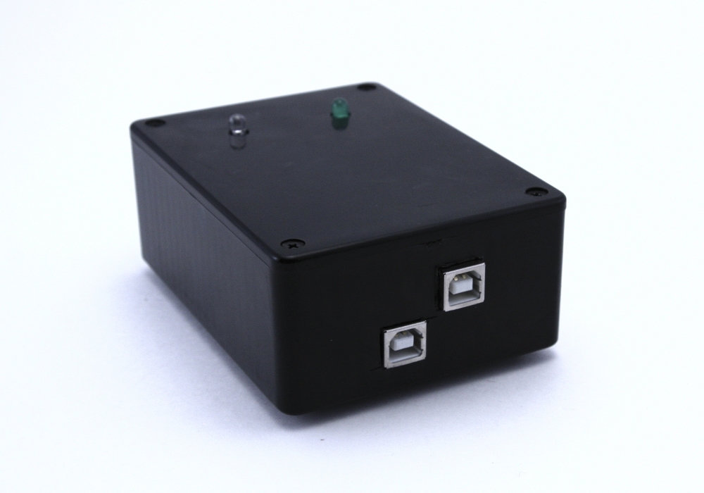
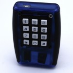
To my computer, its simply a USB keyboard, nothing less, but to me its a remote I can use on any platform with no line of sight. I decided to name it the keyMote. Sounds a bit odd to my ears but its a fitting name.
Here is how it works. There are two parts to this system, the remote, which is battery powered, and the base, which is hooked up to a computer. The remote is a simple keypad (In the case of the prototype, its a numeric keypad, but really, it could be any interface) with a transmitter hooked up to it. The base, the other end, is a receiver with USB Human interface device functionality, in other words, a vanilla USB keyboard. When a button is pressed, the remote sends the identifier of that button to the base which then looks up in a table the keystrokes this identifier is mapped to and sends those to the computer via USB. What button is mapped to what keystroke is entirely configurable using a serial terminal interface (shell) to the base. It can be anything, Ctrl-C, Alt-Shift-F, PageUp, etc. Getting it to interface with your program is then simply a matter of configuring keyboard shortcuts.
The use case
Here is the actual use case that spawned the idea. I was doing some plumbing work in my kitchen with the computer playing songs in the background. It then hit one in the playlist that I especially hate (but keep for nostalgia), but I was in no position to change it as it would have implied bending out of underneath my sink, walking to my computer and then hitting Ctrl + Shift + Right to skip to the next tune. I use Linux and at that time, the media buttons on my keyboard were not operational, I knew very few remotes would work on my platform and finally, I had no line of sight with the computer, so infrared was out of the question. Agreed, a wireless keyboard would have done the trick, but those tend to be limited in range, and well, they are still keyboards, so you have to do the key combinations yourself and are somewhat cumbersome to lug around. So I thought: Why not get something that will emulate my hands typing the keyboard shortcuts?
I looked around for possible off-the-shelf solutions, but none of them were well supported under Linux; basically they all required drivers and were proprietary and as we all know, anything with a driver is dependent on company support an will get dumped sooner of later. The keyboard idea was starting to get some traction. It was the obvious medium to go with, the USB human interface device standard has been around for a decade or so and will likely stick for a few more but more importantly, it is understood by most OSes. Failing to come across anything that would suit my purpose, I set out to develop one from scratch and after a bit of work (or a lot, depending where you come from), I had what I wanted: a simple, rugged self-contained system with no drivers attached, plenty of battery life and a way to make it type whatever I want. Currently, its mapped to my MP3 player, sound controls, Video player controls and some programming IDE functions. It could very well launch applications, toggle the visibility of certain windows (via the window manager), start scripts; it can do anything a keyboard can do.
The system
The main hardware components are an arduino, a wireless receiver and transmitter pair and another microcontroller hooked up to a battery in the remote. I started off with trying out wireless communication on the arduino IDE but soon converted to C/C++ for the added flexibility once I was past figuring out the libraries.
Base
The base software is mainly an interface between two libraries, VirtualWire and V-USB along with a shell to configure the mapping between remote key codes and key strokes. VirtualWire is a library that makes exchanging bits (a lot harder than the datasheet implies, what you send on TX is quite what you get on RX) between vanilla wireless interfaces very straightforward. V-USB is a marvelous implementation of the USB protocol on the AVR using nothing but bit-banging. It’s quite limited in capacity but it’s extremely lean and makes USB accessible for anyone with the patience to understand the protocol. While the actual serial shell is a fair chunk of code, it is needed only for configuration, so this project is mainly composed of glue code and basic electronics. The arduino’s USB connector is used for serial shell functionality, where using commands it is possible to consult statistics about the system, get debugging data, but more importantly map key Ids to key strokes. The other USB connector is the actual keyboard.
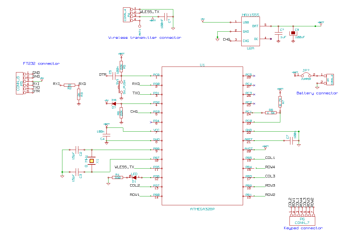
The base schematic
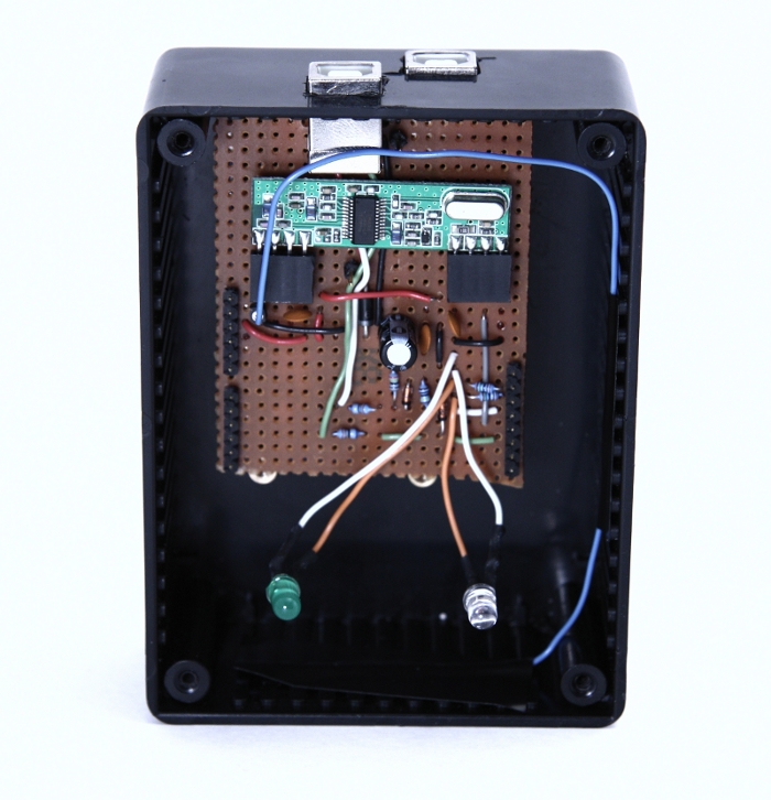
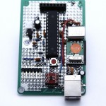
Since I had an arduino to spare, I decided to implement the USB and wireless interfaces as a shield rather than build a specific circuit. Really, the only hurdle was the weird spacing between pin 7 and 8 (why?), but that got solved by soldering angled headers to the side of the perfboard at an offset with the holes they would normally fit in. The wireless receiver was a breeze to connect but the USB interface was slightly more complex, with a couple of zener diodes and resistors to get the correct line levels.
Two versions of the base were created but they only differ in the way they look.
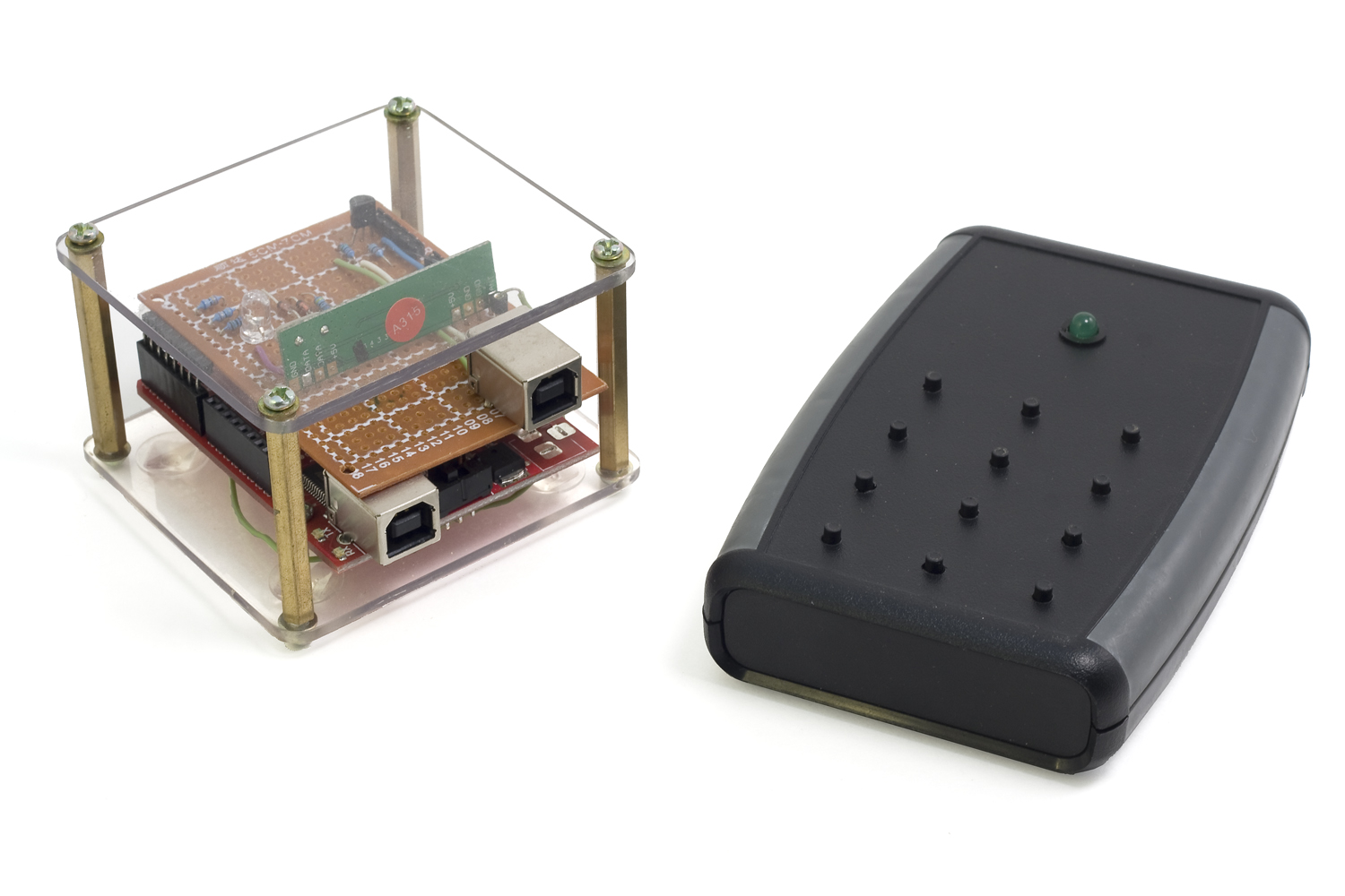
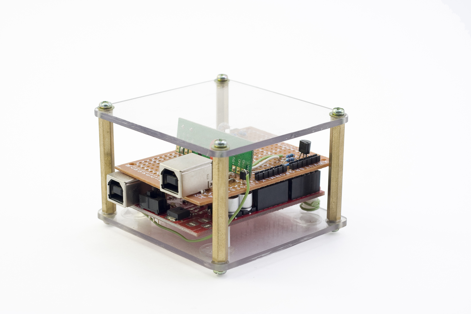
Base version 2
Base version 1
Base version 1 opened
Remote
The base is mostly software but the remote is mostly electronics. The code is essentially a loop that intercepts keypad presses and sends them out through the transmitter to the base. Since it’s battery powered, the complexity of the firmware lays essentially in the power management code as the electronics cannot be left on running at full power all the time.
Remote prototype schematic
I built two different versions of the remote. The prototype which used another ATMega328P (same MCU as the arduino) featured an off-the-shelf keypad and a USB connector with a MAX 1555 for charging. The MCU is left in its deepest sleep mode all the time and is only waken up when a key press occurs. As a result, power consumption is in the order of nano amperes which yields a battery life of a couple months under normal usage when hooked up to a 900 mAh LiPo battery.
Remote version 2 schematic
The second version goes even further into increasing battery life. The ATMega328P, overkill for this application, is replaced with an ATTiny84 and the keypad interface is hooked up a circuit that turns on the micro controller and the transmitter from a fully off state only when a key is pressed. It’s using the same battery as the prototype but the power usage is so minute that after close to two years I have not yet exhausted the battery and measuring the drain is beyond my multimeter’s range. Granted, usage has been on and off due to me leaving for extended periods of time but still, that’s a pretty decent statisctic. So much so that I had plans to convert it to a solar cell and supercapacitor design but sadly, all my prototyping efforts led to failure.
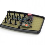
Remote prototype
Internals of the remote prototype
Internals of the remote version 2
The result
It was quickly put together and yielded a result of fairly high quality and convenience for the effort. I’m not saying there is no room for improvement, but it was refreshing to do a project that was not plagued by unforeseen complexity and feature creep. I’ve been using both remotes for the past two years and have been getting months of battery life for the prototype and for its successor, well, it’s still running after two years. Range wise, I can send commands at a distance of about 10 meters through several walls so it more than sufficient.
Since I have no plans to revisit the project in the near future, I’m publishing the source code and the schematics (made with gEDA) up for download on a GNU GPL license. Take note that some of the third-party libraries use a different license which is specified in their respective folders. Should you have any questions, do not hesitate to reach me through the comments or the contact page.
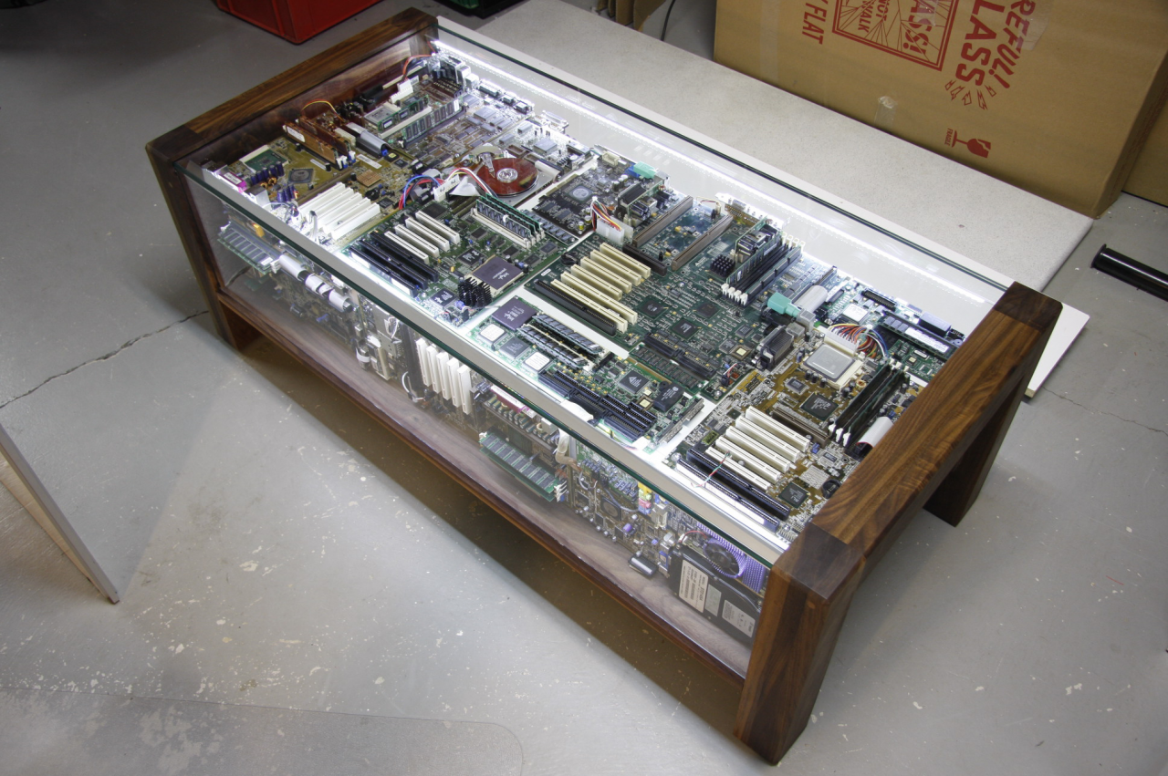
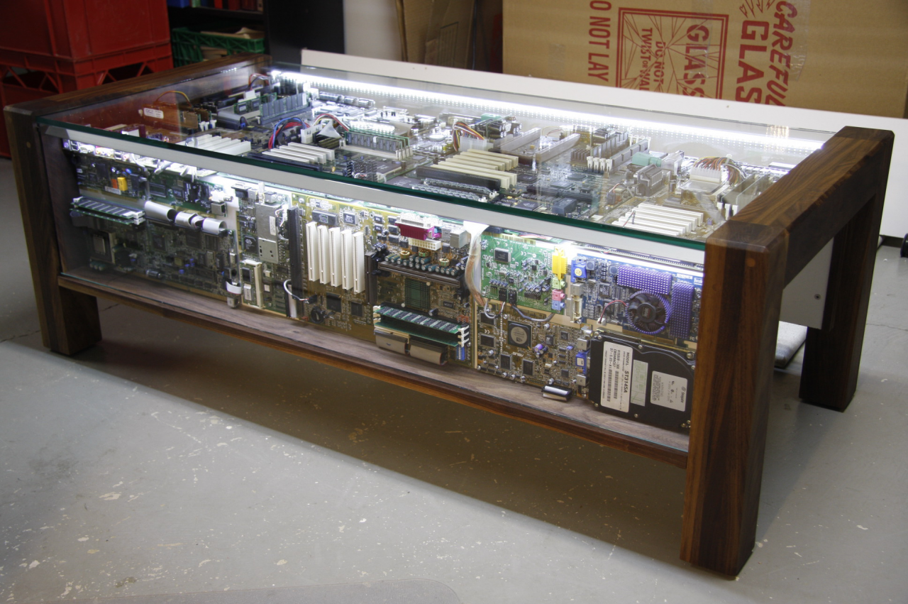
A close up of the finished table with its lighting on.
I’ll admit I’m a bit of a hoarder when it comes to computer parts. Over the years, I have collected a fair amount of equipment with the hope than one day, some of it might come handy. Well, a GeForce 3 from 2002 is not like wood scraps or loose electric cables, the more time passes, the more it becomes useless. Standards evolve and with them connectivity; there is just no way this type of video card will fit in a modern computer (now that everyone uses laptops too). I have had a need for small servers for some projects and an old PII with linux on it would have made a perfect candidate, but then again, the power consumption of those machines are just not worth it. A small embedded computer or shared hosting would pay itself back in no time.
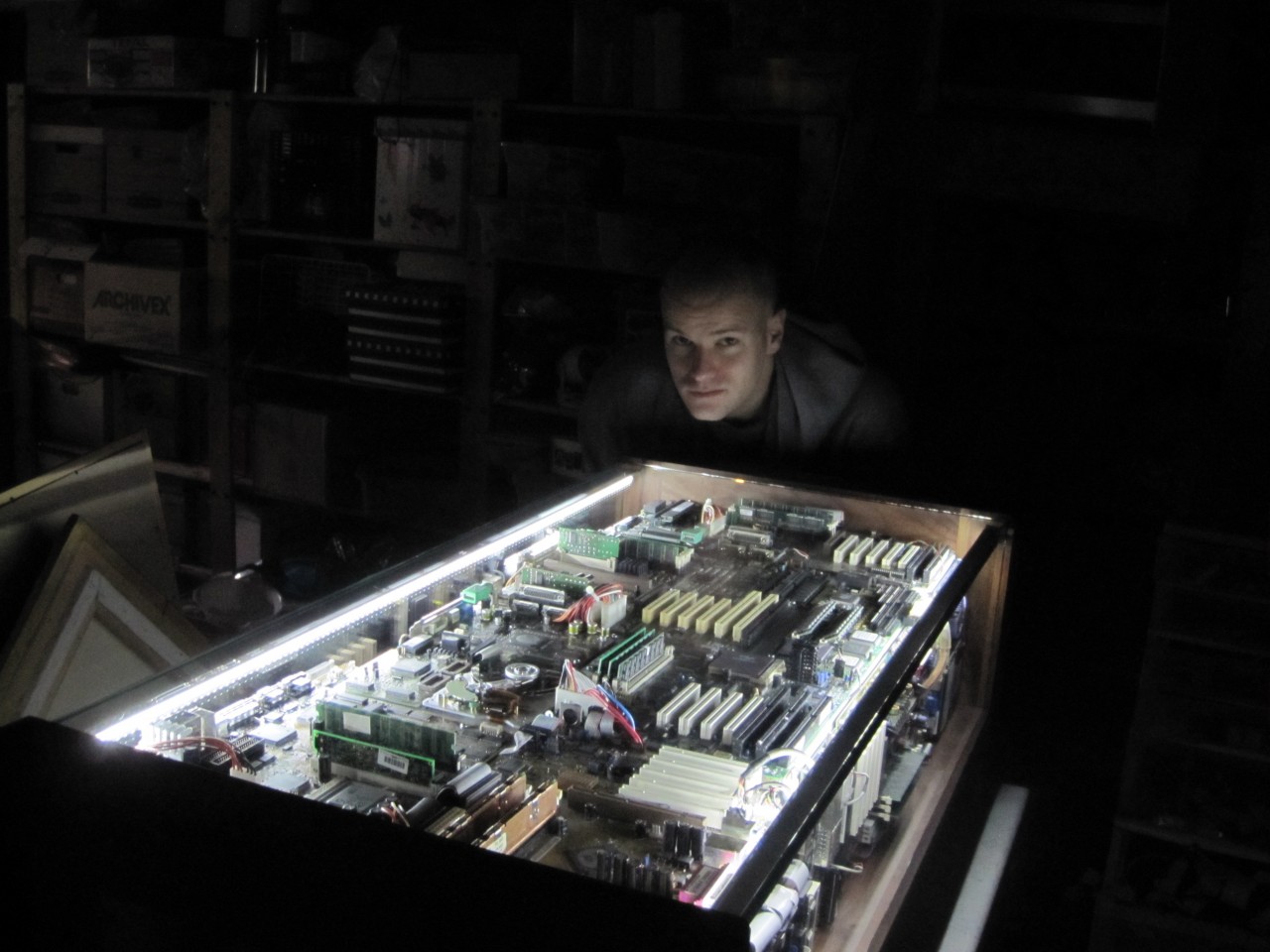
One day, I came across this project through Make and thought it would be a perfect way to give purpose to all that junk, especially that like the inventor of the first table, some of it was from my first machines and while it was now devoid of computational value, still retained sentimentality. Electronic circuits have a mesmerizing power for the knowledgeable and the profane likewise. While staring at an A7N8X for hours will not give the non-engineers any further understanding on how bits are turned into pretty pictures on a monitor, it could nonetheless spark educative discussions on the general role that it plays into this process and at least help dissipate the “black box” effect of modern personal computers. So I proceeded to file the link in my ideas folder, knowing I was then lacking the woodworking skills and tools required for this type of project, and at the time not really thinking I would ever come to have my own computerpartscoffeetable.
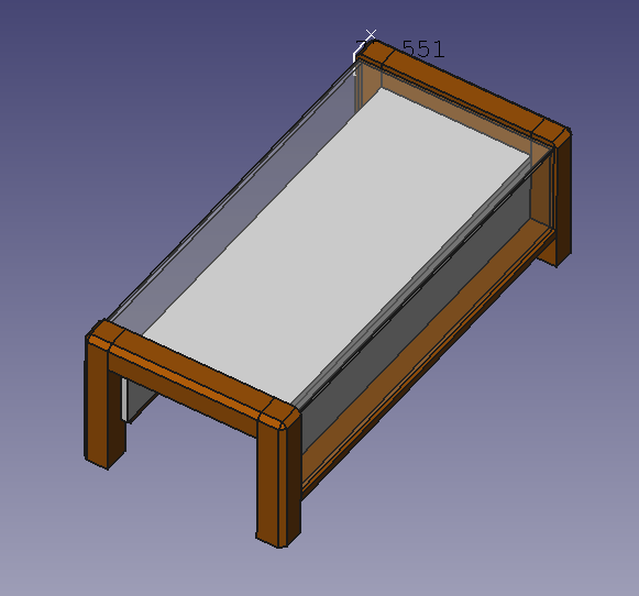
A CAD plan of the table. Save a few millimeters, the end result is the exact same.
Coming back from some time in Europe and having only worked with my brain for over a year (except for this project), the time felt right for a physical challenge. Drawing inspiration from this other computer parts table, I opened FreeCAD, got drawing and in an evening came up with a design of my own: something less imposing, with more modern lines, all without sacrificing the “sarcophagus” effect.
This is not a how-to so I will spare the building details but for those that are interested, feel free to download the CAD file, leave a comment or write me. Basically, the table is build around a frame of particle board which also serves as the bed for the parts. At both ends of the frame are two dark walnut glue-ups with some chamfering all finished with several coats danish oil. Frankly I was not expecting the end-result to be so stunning, the images do not do it justice. The panes of glass fit in a grove carved in the leg members and with the top glass being 10mm (3/8), this makes one solid and stiff piece of furniture. It takes two fully gown men to move it around.
The table is lit up from two led strips at a 45 degree so they can illuminate both the top and their respective side. Powering the strip is the actual only functional circuit of the whole display: a switching power supply I built for the occasion (also something that had been sitting on a shelf for a couple of years).
Money-wise, the project was a bit on the expensive side. I did maximize reuse and recycling, but as every woodworker will confirm, precious wood will cost you, in fact a lot more that what is normally found in hardware stores. Add to the total the price of thick custom cut glass panels and the addition is somewhere around 400$. A coffee table at Ikea is a tenth of that price, but the commonalities ends with function: there is nothing like the quality, craftsmanship, the beauty of a solid piece of wood furniture.
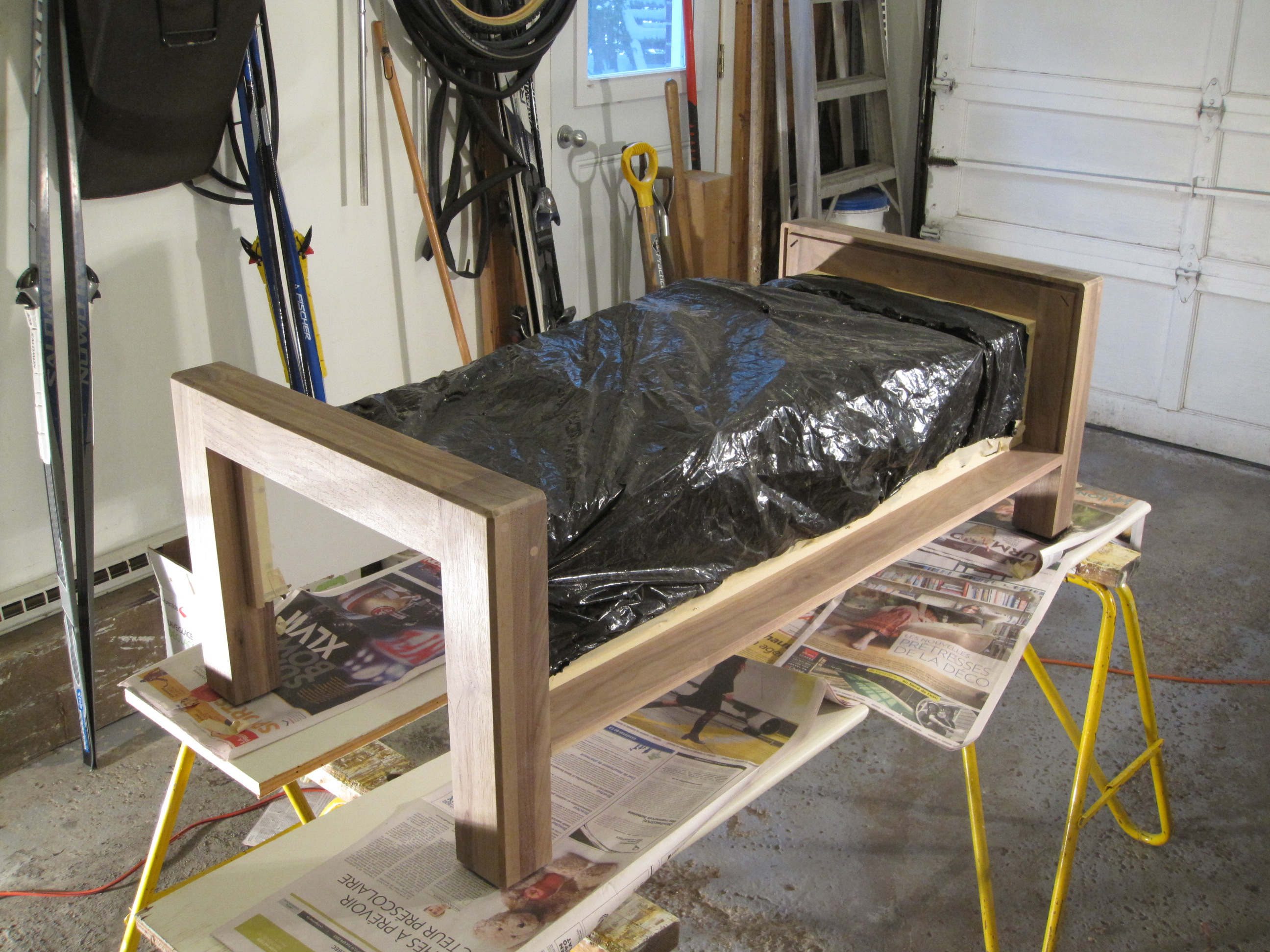
Since I am travelling again and did the finishing touches the day before my departure, I cannot provide a picture with a few happy people around some empties. For now, it is quietly sitting in my workshop under a protective blanket, patiently awaiting my return for merry moments with friends or a lazy coffee the Sunday morning after.
A close up of the finished table with its lighting on.
The finished product.
The look of a satisfied maker.
Giving the table coats of danish oil.
Making sure everything is going to fit together.
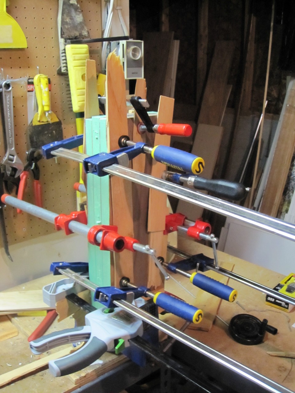
Gluing up the boards together. These boards were then sawed in half to make the leg assembly members.
A CAD plan of the table. Save a few millimeters, the end result is the exact same.
The Joule thief is a really fascinating circuit, simple yet very intricate. Basically, it’s a step-up converted in its most elementary expression. I will spare you the theory since there is plenty of information on it on the web; rustybolt.info is a good place to start.
Joule thieves in all sorts of forms have been featured countless time on DIY websites and I felt it was time I build one. However, I did not want to leave the circuit at the breadboard stage because as it stands, the joule thief has characteristics that make it very attractive for all sorts of low power applications and I figured a flash light would be a very good home for a joule thief, where having the option of using dead batteries is certainly a big plus not to mention using less cells because the circuit steps the voltage up. Why dead batteries? Because a battery is never really dead, its voltage just falls down logarithmically until it hits a point where the device it was powering up stops functioning, which does not mean the battery is totally drained but rather that its voltage has fallen below a usable level. Since joule thieves are step-up converters, they can take that “dead” battery, and give it a new life by stepping up its output voltage to usable levels again.
The build
A 2 AA batteries Maglite
For my flashlight, I opted for a maglite body for its sturdiness and simplicity. I have been using those for years and they have served me well, but with traditional incandescent lamp bulbs (I do know they make LED versions now), they eat through batteries like crazy. So the challenge was to convert a 2 AA battery maglite so it could run off a joule thief circuit and a single AA but could easily get converted back to using a lamps(As I will tell later, the joule thief’s light output is not so strong … sufficient in most cases but not strong).
As I would be using one less battery, the trick was to use that space to hold the circuitry. I proceeded to cut a perfboard the size of an AA and soldered all the components on it with the heads from two nails as connectors. Inductors being already pretty hard to come around, one tailored to this application would be next to impossible to find so I had to hand wind one using 20 or so turns of 40 awg enameled wire (almost hair thin (also hard to find, look for it on ebay)) around a ferrite core to build the joule thief’s coil. Once everything was in place, I soldered the circuit ground wire, which when making contact with the flashlight’s body, would turn it on or off. That wire had to be routed inside the plastic insert that normally holds the lamp and its metal pad in place so that when you turn the head of the maglite, it screws up and presses the pad against the body, thus closing the circuit. In order to allow the maglite to be converted back to using a lamp, I just cut a notch under that pad so that pressure on it would contact the wire and ground it.
For protection and isolation, the circuit was wrapped it with acrylic tubing (some leftovers from the time my computer was watercooled) and inserted in the body. Finally, I installed the LED at the top, with its two pins bent to fit in the holes normally meant for the incandescent bulb. The lens fits perfectly on it; the only way to tell it’s a modified maglite is to look at the bulb.
The circuit being constructed.Testing the circuit.A correctly working joule thief.The finished circuit in its protectective acrylic tubing.It works!
Results
I will right away admit that I am a bit dissapointed with the light output of the circuit. Though I did expect it to be a whole lot less than the incandescent bulb, it is barely usable. The culprit is certainly the LED. At only 3mm, it can only do so much with that waveform going through it ; it’s rated for 20mA and its getting 12 so the circuit is doing a correct job keeping in mind that joule thieves are quite inefficient ( in the order of 30-40% judging by the duty cycle). Using a larger inductance is out of question because it reduces the frequency without modifying the waveform but using a larger wire gauge (thus lowering the resistance of the coil, see below) would probably help. What also does appear to make a difference is the type of transistor used, I noticed that the current draw of the LED was only 9mA with a 2N3904 while it jumped to 12 with a PN2222A. Both are general purpose NPN so maybe another type of transitor would do better. As a side note, the circuit will not work with FETs, I have found plans to build a joule thief with those but its much more complicated.
With a single battery at 1.435V, I got two days of continuous lighting, not bad. At that voltage, the current draw is about 65mA. I was not able to measure the pull of the standard incadescent bulb for comparison because the inline resistance of my multimeter was too consequent, but one interesting thing I noticed was that below a certain voltage, the light would start to flicker at hertz or so. Its hard to see in the picture, but I added an electrolytic capacitor for bypass; it could have something to do with that.
Even though I said that the light output was nothing to brag about, I did take the flashlights to many trips in the woods, with some lasting a few days and it has held up perfectly. With your eyesight accustomed to the dark a bit, you can see at a few meters and whatever task your hands are doing is lit well enough for comfort. With all this serious usage, I have not yet ran out that dead battery. Too bad, I wish I could have gone out asking my hiking buddies for dead batteries.
With LED flashlights being quite effective, I can’t vouch for the potential of this circuit for such applications. Certainly, using dead batteries is a plus as they are relatively easy to come by, but the low light output would certainly be a killer for most of us because when it comes to photons during a moonless night in the woods, more is just better.
According to rustybolt (thanks), my coil is mainly to blame for my poor performing Joule thief. The wire used is too thin and has a consequence opposes too great of a resistance ( I should have tought about that) to the current, thereby limiting the LED’s brightness. There is a very clear article on Joule Thief coil selection on his site. He also points to the transistor being responsible for the loss of efficiency. Next time I get my hand on that maglite (I’m travelling right now so it’s an ocean apart from me), I’ll revisit the circuit.