

One of my friends, who creates music as a hobby, recently bought a pair of AKG 601 headphones. While I do listen to a fair amount of music, I would not consider myself an audiophile or anything close to that. However, those headphones do make a difference I can notice in the quality (or lack thereof for low bit rate MP3s) of whatever is being played. There is only one small problem with them. Being massive open headphones, my friend’s sound card is only able to put out an acceptable level of sound at maximum volume; his MP3 player, on the other hand, is simply incapable of driving them. The AKG 601 have a rated impedance of 120 Ohms while normal earbuds seem to be around 20. As a result of a soundcard’s output impedance being too high, a normal speaker output is not capable of providing enough current to the headphones.
They are huge, expensive and leak a lot of sound, so he does not plan to use them on bus rides, but there are still some serious downsides with having to drive them at maximum volume:
- Levels of distortion increase significantly as maximum power is reached in an amplifier. This means that running the volume at maximum produces sound of a lower quality than if it was outputted at 50% and then passed trough a more capable amplifier.
- When he creates music and wants to listen to specific instruments or tracks that are not as loud as the rest he is stuck with the current level of volume.
To address those problems he was considering purchasing a headphone amplifier, but to me, this seemed like the perfect opportunity for a diy solution. As he is not at all familiar with the world of electronics, I offered myself for the task as it was a good and easy way to get my hands dirty with pure analog stuff and get acquainted with audio. My background is more software with the occasional digital circuit. I did learn about all the concepts in application in this project at school, but the retention capacity of my brain decreases significantly when the interest is not there, and a bunch of formulas splattered on a white board does not tell me how to use an op amp in real life.
Since parts are cheap and shipping isn’t, I decided to build one for me as well. This post details the process but its not a how-to for the CMoy as there are alrealy a ton around the web.
Circuit
I started my research on the excellent diyaudioprojects.com and found the CMoy/Grado RA-1 project. The circuit looked simple enough and according to the author, the quality was on par with a Grado RA-1 which retails at 425 $US on amazon. It turns out that the CMoy pocket amplifier, named after Chu Moy, its inventor, is a very popular design. You can find kits for it on the web that are about an order of magnitude cheaper than the RA-1 it aims at emulating.

Chu Moy’s website provides a wealth of information, but the one that help me the most by far was Warren Young‘s tutorial on the CMoy.
Do not let yourself be fooled by the simplicity of this circuit, there is a lot more to it than meets the eye and tangentsoft’s tutorial does an outstanding job at explaining all the specificities and what you need to be concerned about when making modification. It took me about ten minutes to get a working version on a breadboard, but actually understanding it required a fair amount of reading and thinking. Once again, Warren’s site proved ato be invaluable resource in this, especially his audiologica section. Some amplifier designs on his website are considerably more complex than this one and would be a nice progression from this project.

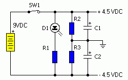
- Power supply circuit

The power supply is no too complicated but somewhat unconventional because of its use of a virtual ground, something that was previously unknown to me. My design is generally the same except for the addition of a linear regulator and a protection diode as I did not want to run it from a 9V battery and the wall wart I had lying around was unregulated. For the amplifying part, I added a resistance in parallel with the volume pot to make it behave in a more linear fashion (I bought a log one), some decoupling ceramic caps for the op-amp’s supply lines and upped the value of C1 from 0.1uF to 1uF to let trough lower bass frequencies. Every CMoy amplifier circuit variation uses different resistance value. R2 is fairly constant at 100kOhm as it forms toghether with C1 a high-pass filter. R3 and R4 will vary depending on the gain required. The power supply part is pretty straightforward but you will need to find a value for R2 and R3 that will strike a good balance between not draining the battery too fast (should you choose to go that route) and providing the virtual ground enough current sink capability.
Power consumption is very low. I am using a 9V unregulated wall-wart with a current rating of 100mA. Since the amp cannot load it fully, the output voltage at the connector is around 12V which leaves plenty of room for subsequent regulation down to 9.5V. The linear regulator is an absolute necessity as its omission lets trough a very audible hum.
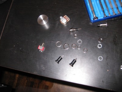
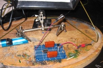
While this circuit will work with any standard parts (which I used for the prototype), it is best to use audio grade components. This is often synonym of overpriced, but in this case, since we are talking small and simple, you can get away with only investing a few more dollars. For the op-amp, I selected the Burr Brown OPA2134 as recommended by CMoy and decided to go with polypropylene metal film capacitors instead of polyester. I also got a gold-plated IC sockets and audio jacks. The only non-standard part was the volume pot, which had to be dual-gang in order to control both channel at once.
Prototype

- Protype with generic components

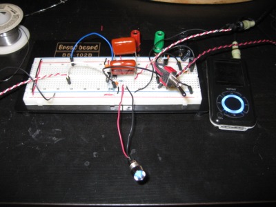
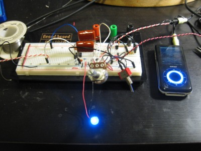
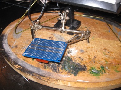
Naturally, everything stated on a bread board. There is nothing spectacular about that, but when I first put toghether the circuit, all I had to work with was some general purpose op-amps (MC1458) and some electrolytic caps. I was unsure whether the op-amp would be sufficient or not, but I did know electrolytic caps are only to be used in a bypass configuration as they induce a fair amount of distortion when used in line. Regardless, there was improvement in comparision with not using an amp at all. At this point, I became confident this would not be another useless circuit and things could only get better with the “audio grade” parts.

- Prototype with audio-grade components

When I received the components I ordered from mouser specifically for this project, I instantly swapped them on the protoype and was rewared with a increase in quality… or so I think. The term “subjective” applies especially well to the audio realm; due to known psychological effects, me knowing the components were actually better in theory rendered me incapable of judging whether there was an improvement or not. Then again, I do not really know what to look for but I would consider the overall difference to be subtle enough to be affected by skewed perception. This is why I decided to take my friend trough some blind tests. He does not know a capacitor from a resistance and much less their potential effect on sound, on the other hand, he know music and most likely has a more discerning hear than mine; he is the perfect candidate. More on that at the end of the post.
Enclosure
")
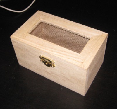
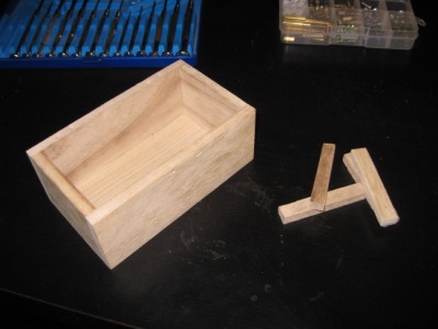
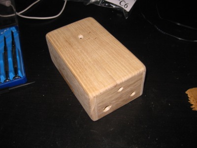
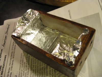
- The original box
")
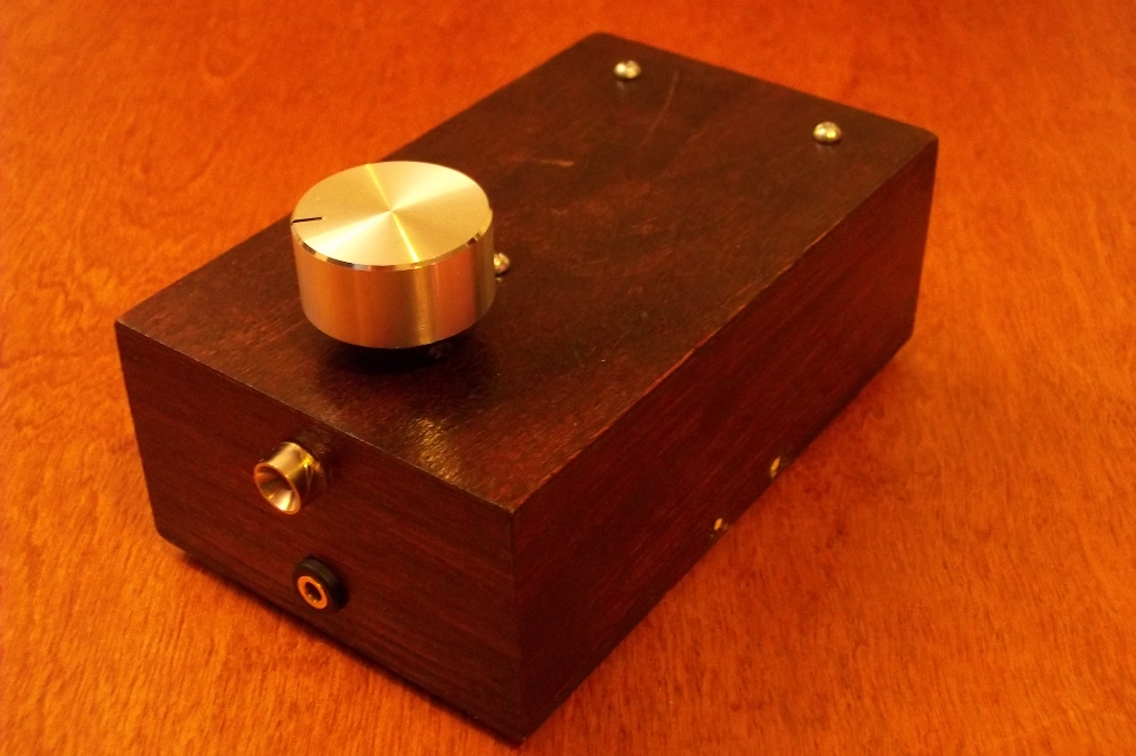
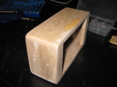
While the parts were on their way, I decided to get started on the enclosure right away. Naturally, I would have gone towards a plastic project box but while me and my friend were discussing the project, he suggested the use of a small wooden chest as he had one handy and felt a tupperware container would not do a piece of quality audio equipment any justice. Upon inspecting it, I figured it would be pretty easy to turn it into something visually pleasing with a bit of woodworking. I found my box at Michael’s for $3.50. I had never worked on wood (except while renovating but I would not consider this woodworking) so I was somewhat unsure of the end-result. With perspective, this is the prettiest project enclosure I have built so far and for that price, I’ll definetly repeat this design.
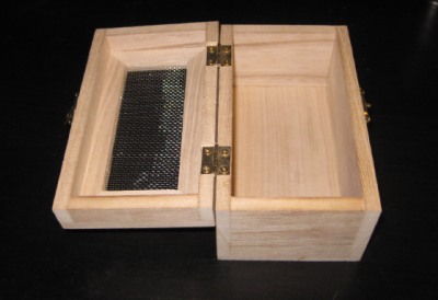
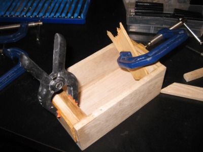
 The box went trough several modifications. First, the lid was removed and disassembled. The rectangular pieces of which the sides of the lid were made were cut and glued to the box. Two there added to the opening of the box to provide a bit more support for feets while the two others where glued to the bottom to raise the pcb.
The holes and marks where the hinges and lock used to be were filled with wood filler and then the edges were sanded down to give the box a rounder shape. Lastly, holes to accomodate the various connectors and holders were carefully (pine is very soft and chips easily) drilled.
 Since the box was made out of pine, it needed to have wood conditionner applied on it. It took me a while to figure out how to use this product as information from some diy sites conflicts with the manufacturer’s label and everyone seems to have their particular process when it comes to preparing soft wood for staining. I finally came across a site that explained that wood conditionner was actually diluted varnish. Consequently, it needed a day of drying to properly seal the wood’s pores and allow even stain penetration. This contradicted the can’s label which directed to apply the stain within two hours of applying the conditionner. I ended up following the website’s advice and let it dry overnight. The stain came out beautiful and uniform without any blotching while tests using the manufacturer’s instructions on scraps where not so conclusive.
After staining, I applied two coats of polyurethane warnish with some light sanding in between and that was it for the box. It took three days including drying time but overall, I would estimate the amount of time invested to two hours with sanding being the longer task.
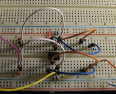
Soldering
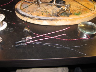
Soldering the circuit was somewhat harder than usual because of the PCB I used but with any

standard board this should be an easy task. The routing is straighforward but ideally, everything affecting the signal path should be kept as close as possible so as to avoid the side effects of long wires (inductance, capacitance, EMI pickup). Mine required a fairly sized board because of the polypropylene capacitors, but with small components, everything should fit on two postage stamps and not take more than two hours to solder.
Finalization
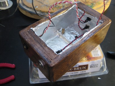
To block any unwanted EMI, I lined the inside of the box with two layers of aluminium foil glued toghether like Mark did on his CMoy/Grado RA-1 project. Whether this is useless or not I cannot tell, but it certainly cannot hurt. I still have some old CRTs at my parent’s place so when I get the chance, I will try and see if it picks up anything.

Installing the circuit in the box is no simple task as all the connections have to be soldered while it is in there sitting in mid air. Incidently debugging also has to happen in this position. Mine did pass the smoke test but it did not work correctly the first time around. It turns out I had soldered one channel of the pot the wrong way.
Sound
As mentioned in the intro, I would not consider myself versed in the art of listening and I much less have the capacity to describe sound with words. However, I can certainly tell it makes a noticeable difference in quality of the music. Even with my old and battered Koss headphones it sounds better but when I got to try it with my friend’s AKG-601 I was blown away and felt for a minute I should make the investment and get myself a pair.
The downside of better sound is more obvious compression artifacts; a good amplifier will not discriminate either. Some of my tunes which sounded fine on my MP3 player with earbuds are now barely listenable because of the effectiveness of the amp at reproducing what it takes as input. I finally got a around to finding a few MP3 in my collection which were of good quality, but you should nonetheless be aware that if the end product sounds bad, check the MP3s first before probing the circuit for a problem that isn’t there.
I have only listened to it for a few hours so far and apparently, it get’s better with time as parts burn-in (like engines??). This seems odd to me, but I will take the web’s word on that. I could somehow see this phenomenon coming into play with tubes and high-powered solid-state amplifiers as they are genereally under a lot of thermal stress but for this little mW scale headphone amp, I have my doubts.
(Scientific) Test
Yes, it does sound better, but that’s only my opinion. And a very biaised one because I researched and built the whole thing and incidently, would be very disapointed if all that work did not pay off. It certainly feels like adding the amp to my listening set-up improves the sound, but you can only live with a placebo effect for so long, so I got two friends including the one for which this project was started in the first place and did a blind test.
There were initially four configurations but we decided to drop one for fear of not completing the test before the beer store closed:
-
Straight MP3 player
-
MP3 player and prototype circuit (no audio-grade components)
-
MP3 player and finished amp
The headphones were obviously the same for all tests and the volumes were adjusted to approximatively the same level. The MP3 player when used alone had to be set to its max volume which is a good thing since the whole purpose of the headphone amp is to avoid this as it dramatically increases the distortion level.
A run would consist of 1 minute of listening to the same song (Californiacation by Red Hot Chili Pepers; everyone I know likes this song) on every configuration. The subjects did not know which one it configuration they were listening with, all they could see was me shuffling wires behind a box and then handing them the headphones. We repeated the run three times so as to increase the chances of getting a statistical significance.
One subject got discouraged in the middle of test, complaining that it all sounded the same to him but despite his lack of faith and to his amazement, the results confirmed the predictions. In order of quality:
-
Prototype
-
Finished amp
-
MP3
The rating scheme was a sort in order of preference, but one decided to rate using half marks so the results group the two amps closer toghether. The MP3 player was identified as worst every time while the two amps shared the top two almost equally. I would have expected the finished amp to come out first but after some careful listening to the actual track, I realised compression artifacts were more audible on it. This is probably due to the OPA2134’s better bandwith as artifacts are generally found in higher frequencies. The MP3 player just by itself did sound truly awful, Some artifacts were not present while others were exacerbated but overall, it felt a bit like listening to the FM radio.
Conclusion

Simple, quick and inexpensive projects are definatly a rare occurance in my life, so this one was definetly a welcomed breath of fresh air; its nice to finish something and it gave me a break from battling with C++. It is not perfect yet but when I get the motivation, I’ll get to correcting the small bugs: mainly a minute discrepancy between the left and right gain (resistor/pot variation) and a not linear enough pot. For the time being I’ll just enjoy it as is.

Building audio equipments is definelty something I will revisit in the future. It’s a break from routine and a very gentle way to get familiarised with the mysterious and unpredictable field of analog electronics: everything works at a low frequency and a low votlage so you can be confident nothing extra weird is happening. As a plus, you get something useful at the end of the day. To summarize, this project is the perfect “Hello world” equivalent.
Next step will be a full scale amp with some digital controls; the circuit is putting itself toghether in my mind as I write those lines, but it will have to wait for a while as I have other stuff that needs to get finished and still in the process of salvaging components.
My friend’s version

Not that different actually, but it took a while before we could meet (with 500 km separating us) and sit down for a few hours (from 20:00 to 04:00) to finish the project. I had given him a plan and a solder iron, but we ended up completing the project together. In retrospective, there was no way he could have worked on the thing like I hope he would; I even had soldered the voltage regulator backwards and besides that, there we a massive amount of obstacles I strongly doubt someone with no electronic background could have overcome. Still, it was fun getting high on solder fumes along with him. Tests were conclusive and he is now the proud owner of a clone of a 425$-ish amp clone. The one thing we changed was how the volume pot behaves. I had originally bought a log version but found out it was only useful at 80% of its range so I added a couple resistors to make my friends’s pot behave a bit in a more linear fashion.
Gallery


some headphone amplifiers use negative feedback to reduce the noise levels :
Thank you for sharing this project with us.
For people that likes to build electronic circuits, there are many
interesting circuits (audio, microprocessors and more ) on http://www.artic-instruments.com
regards
John
Sorry it was wrong weblink:
The right one is: http://www.artic-instruments.webs.com/
Hi,
Very interesting to read, well written.
Years later, it seems I just made the same Cmoy var. Gwado design, see https://imgur.com/a/ylgmU96.
I choose to use an aluminium box which I built in a plastic enclosure (but perhaps I should have used shielded cable).
This is a prototype, the next one will be smaller (see the last image) and I shall also use a wooden enclosure then.
Best regards,
Cor
Very neat! What is the sound quality like? Can’t wait to see the end result with a wooden enclosure.
Almost one year later I still did not built it in a wooden enclosure. I am not in a hurry because the prototype already sounds amazing, especially listening to flac files instead of mp3.
I added some sentences to my webblog about that prototype, see https://wanderingidea.blogspot.com/2019/03/diy-cmoy-headphone-amplifier-i-rarely.html
Best regards,
Cor
Your plastic / aluminum case does do job it seems :) Also a very nice and descriptive blog post you made.
Cheers!