OD3D stands for the french « Oscilloscope Digital 3 Dimensions » which means Digital 3D Oscilloscope. It was me and my partner’s 4th year university project. Simply put, it’s a completely functional computer based oscilloscope that works on three axes instead of two. This permits more complex visualization of waveforms, especially in the historical mode, where you can see what the signal looked like many samples ago. Any way, If you want to better understand what it does more than a classical oscilloscope, I urge you to look at the video above and the screenshots below.
It was developed under the course of a year mostly during our free time. Even if it did not ranked very well compared to other projects (try to match the bling factor of a motion-sensing automated gun-turret …), we had plans to continue its development until life took us somewhere else (and made us switch to Unix based OSes). Sadly, it sat on our hard drives for more than four years before we decided that it would be a shame to let so much work rot to obsolescence so we decided to release the whole source under a Creative Commons Attribution 3.0 license so someone can hopefully use it in another project or draw inspiration from it.
The goal of this project was to offer greater possibilities in signal visualization, build a complete, powerful and versatile software oscilloscope suite and more generally explore something new. Someone told us it could have interesting applications in conjunction with sonars (3D waterfall display) and we almost go it to act as a semiconductor curve tracer (Id vs Vds vs Vgs).
Short architectural descriptions
The whole project is actually made of two programs, the oscilloscope itself and the generic 3D engine.
We did not get as far as commenting the whole thing. In fact, there are almost no comments at all in the code but if you actually follow the logic and understand the pipeline architecture, you should have no problem figuring out how the oscilloscope part of it works. As for the 3D engine, I suggest you start with checking the demo that comes with it. Furthermore, it is not completely debugged, so you should expect it to crash pretty often.
Oscilloscope
During the actual implementation of the oscilloscope, we tried to abstract things as much as possible in order to make the project extensible. For now, it can only use sound cards or a virtual signal generator as an input, but it would not be too hard to use a USB device (another thing we were working on) or some other custom solution. This also holds true for all the modules that sit in between the source input driver and the actual display (trigger and resolution filter), where the architecture enables you to easily build and integrate one of your own (like a spectrum analyzer or a data logger). The whole thing becomes an oscilloscope when you order and connect those modules in a specific manner: Input->Trigger->Display.
Many Inputs can connect to the same display or many displays can be connected to the same input. There are no limits on the number of channels or displays; you can go as far as your hardware resources will permit you. Back in 2008 when we presented it, we ran it on an Athlon 800 with 256MB of RAM and a GF2 MX400 to show that it was not very taxing on resources. If you want more technical information, go take a look at the specificities section.
3D engine
The 3D engine (named Motr3D) was developed as a standalone solution as opposed to being totally integrated in the oscilloscope, this means that it can be used for other stuff, like in the demo that comes in its executable folders, where we recreated a the solar system. As opposed to the oscilloscope, which is pretty functional, the 3D engine is very primitive and will not get you beyond displaying and moving polygons and basic shapes around. From the start, it was programmed to be as abstract from graphics API as possible (it uses Direct3D but it could be implemented with OpenGL), be fully object oriented and have a runtime architecture like a tree, where every 3D object (even the camera) is part of a tree and inherits from a common type. Even if the project consisted of an oscilloscope, the 3D engine is the part we are most proud of because it was both very challenging (80% of the programming time) and by far the most fun we had programming something. If you want more technical information, scroll down to the specificities section.
Specificities
Oscilloscope
Supports as many channels as your hardware will permit.
Supports as many displays as your hardware will permit.
Abstracted pipeline architecture for modularity.
Can work with any type of input, but only sound cards or a virtual signal generator are implemented.
Programmed in C# for the Microsoft .NET framework 2.0.
Has been tested on Windows 2000/XP/Vista.
3D engine
Fully object oriented in architecture.
Supports many primitives (cube, line, spheres, etc.)
Programmed in C# for the Microsoft .NET framework 2.0.
Works with Direct3D (managed) but can be made to work with OpenGL.
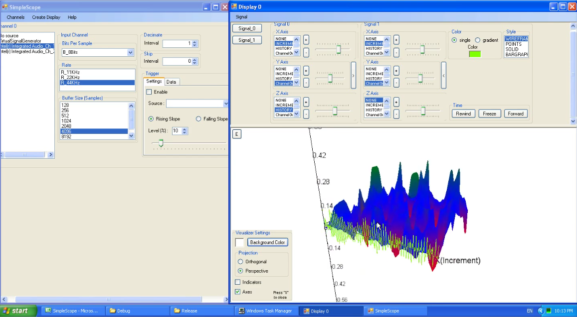
Many displays can be created to mix different signals together. Here, a since wave from a signal generator is combined with the audio souce being displayed in the background.
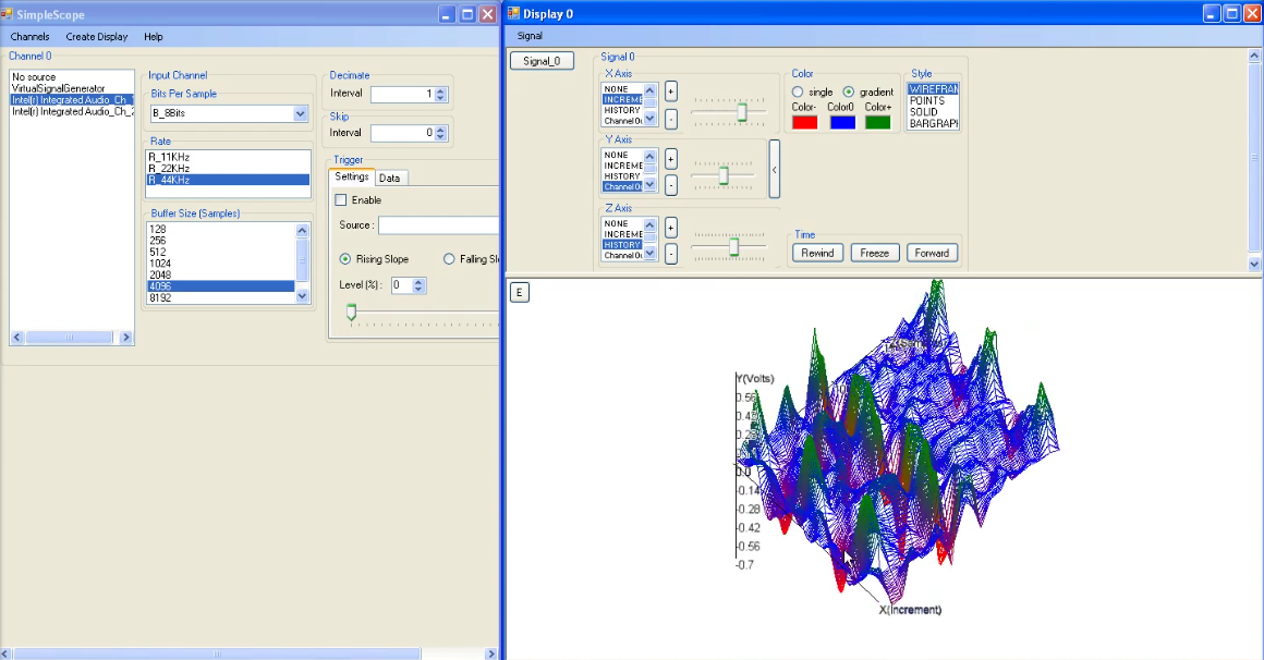
Any number of signals can be displayed at once. Here, a 2D view of the signal in 3D was added to the existing 3D view.
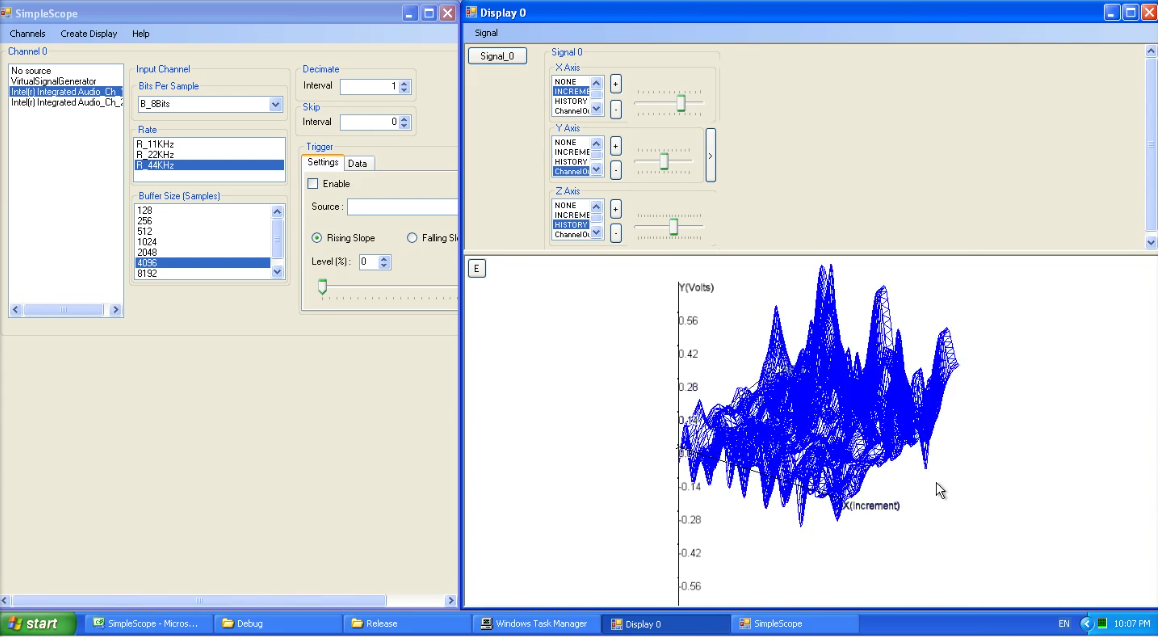
The appearance of signals can be modified for easier visualization
A display of a simple signal in 3D. X is the time, Y volts, and Z the samples. The signal comes from the microphone input of the sound card.
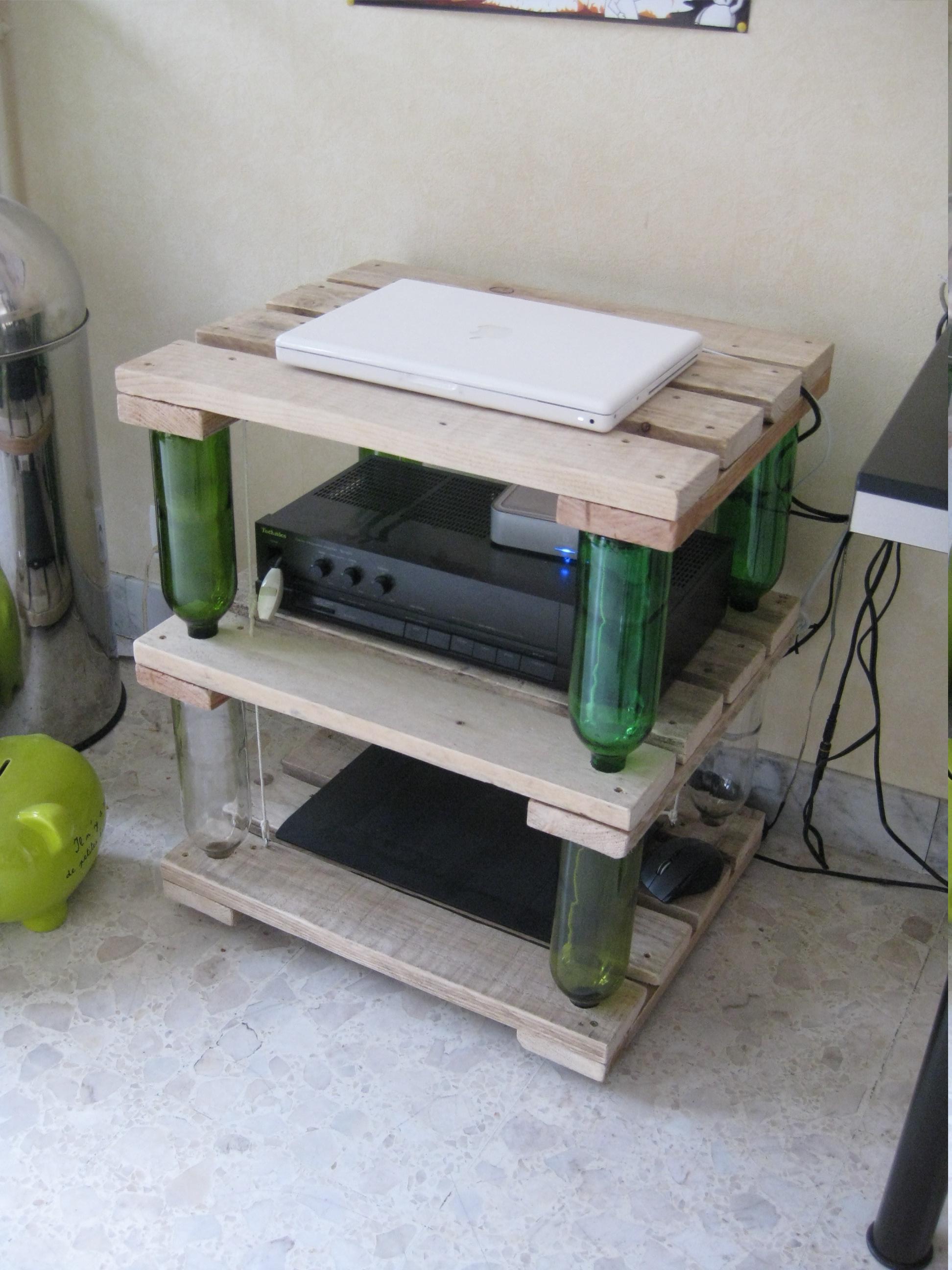
My friend’s apartment in Toulouse, France, was really lacking furniture so I challenged myself to find a design I could build with whatever materials I could reclaim from the garbage, a budget of 10€ and nothing for tools but a saw, some sanding paper, a drill (or the kind of stuff not-so-manual people keep in their toolboxes).
While browsing instructables, I came upon what I felt was the most promising design, the Ten Green coffee table by Zero-Waste. It is built with easy to come by materials (wine bottles and wood), but what I found problematic was the hardware used for the tensioning system, which for the three levels of tables would have costed me at least 50€. While it certainly looks great, it was totally over my budget so upon realization of that fact at the hardware store, I got my brain to work and stated walking up and down the alleys for inspiration and quickly came to figure out a more economical solution with nothing but screw eyes and strings.
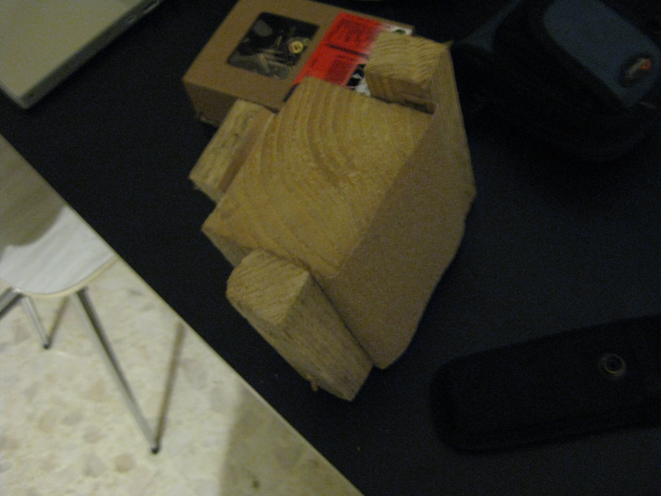
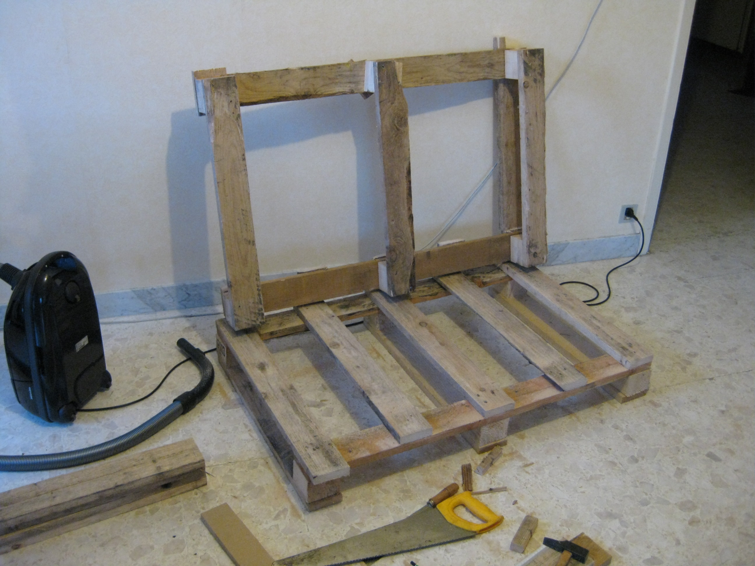
The wood: a pallet
The pallet
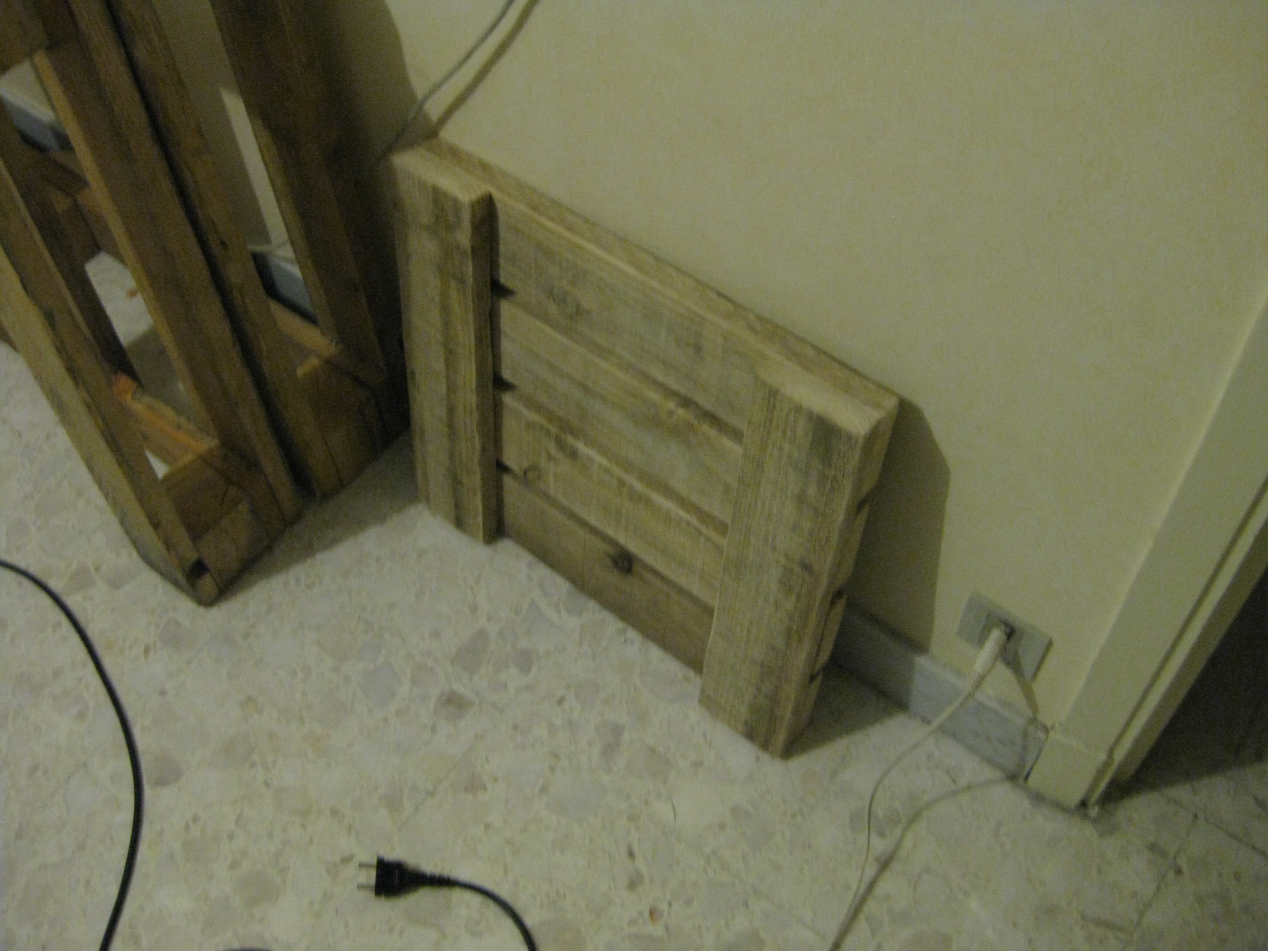
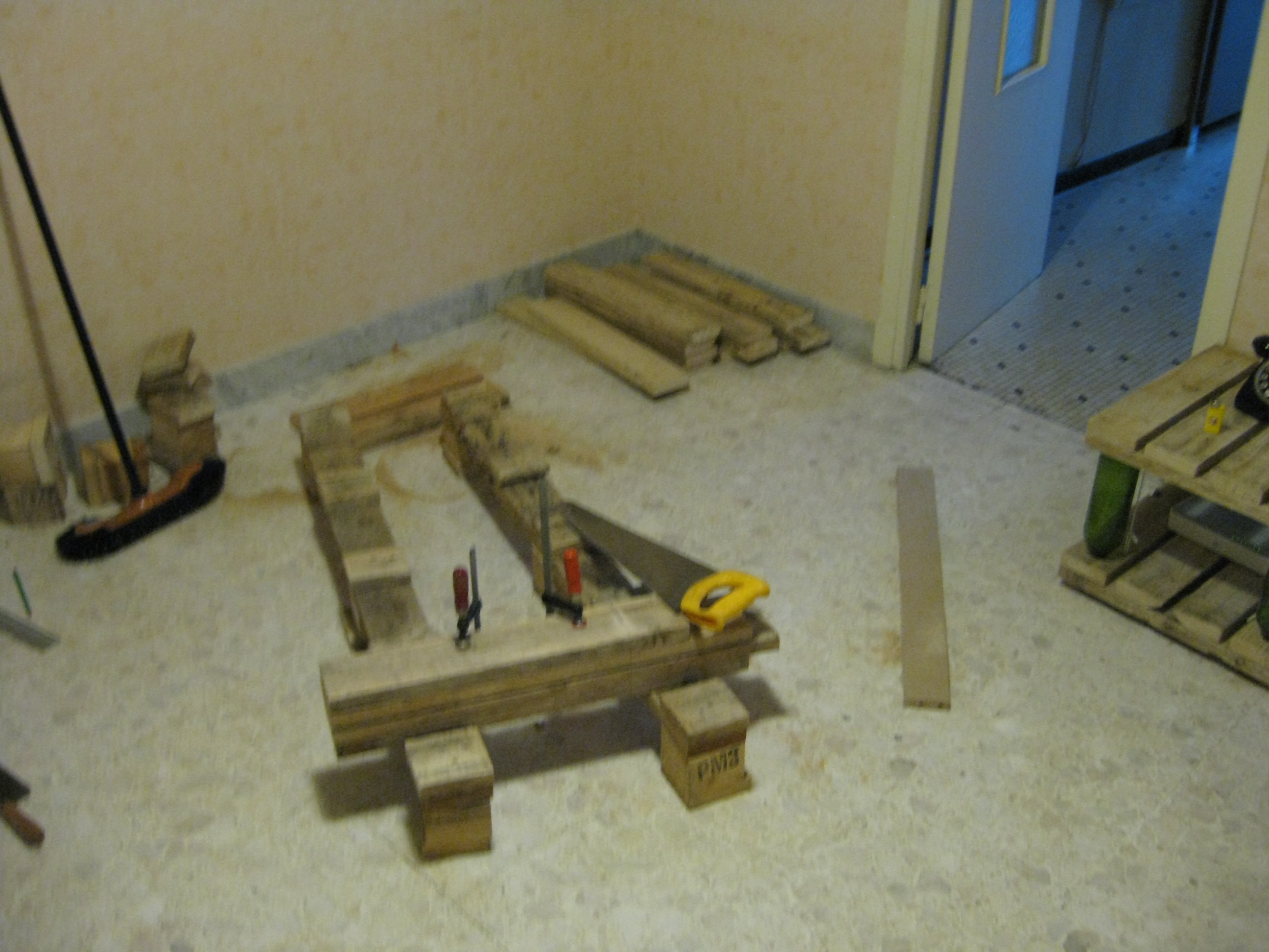
Finding wine bottles is trivial (especially in France), but cheap wood is another story. There were plenty of discarded pallets in the streets, but it took me a while to find a suitable one. It had to be large enough, clean (ie: mostly free of dirt, cement and/or paint) and built with decent quality wood which for pallets is very uncommon. I forgot to take a picture of the whole pallet so this one does not quite do it justice. It was a pain to carry across the city, back-breaking work cutting it and immensely tedious to sand the pieces manually but I managed to build my two tables out of it.
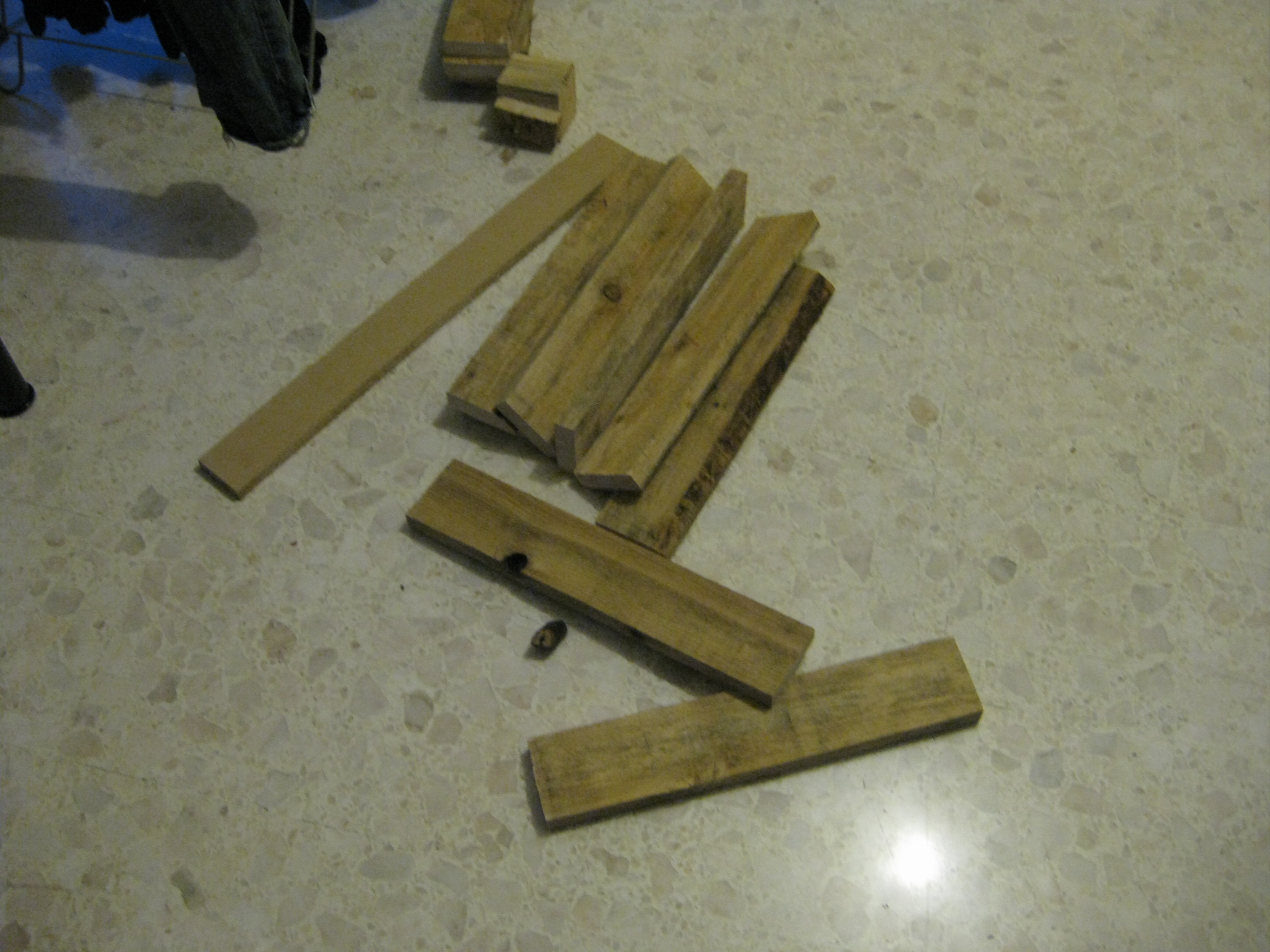
The two surfaces of the first table
Apart from the physical hardships of working without power tools processing the pallet into decent looking surfaces was a piece of cake. I cut up the pallet in even size planks (which numbered 30) and then sanded them down to remove some coarseness (they use very low grade timber). I then assembled them into levels and drilled the four corners of the bottom levels with a hole large enough for the neck of a bottle to fit in.
The wine bottles: Cabernet-Sauvigon, Shiraz, etc.
The part most will enjoyed the most. Be careful though, wine bottles vary in shape between brands so you should buy bottles in four. If you want bottles very quickly ask a nearby restaurant if he can put them away for you and come pick them up after a service.
Assembly
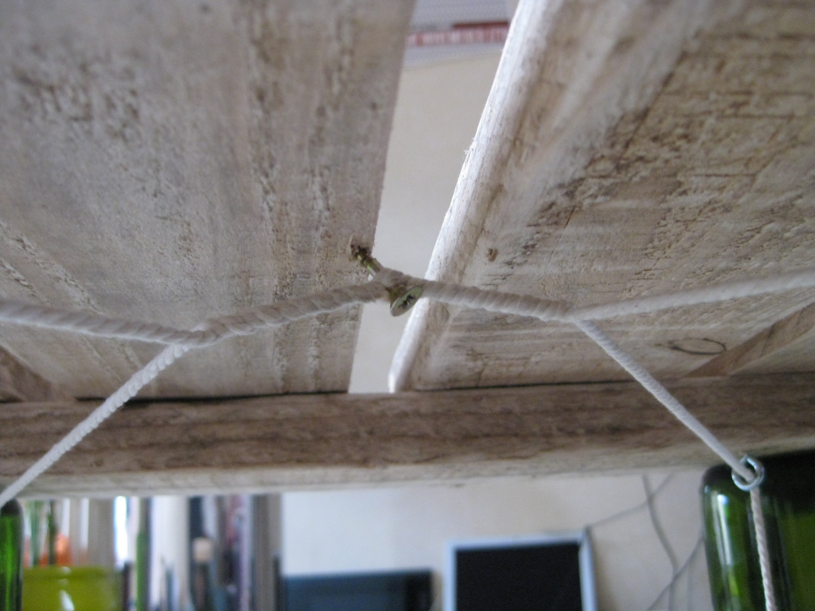
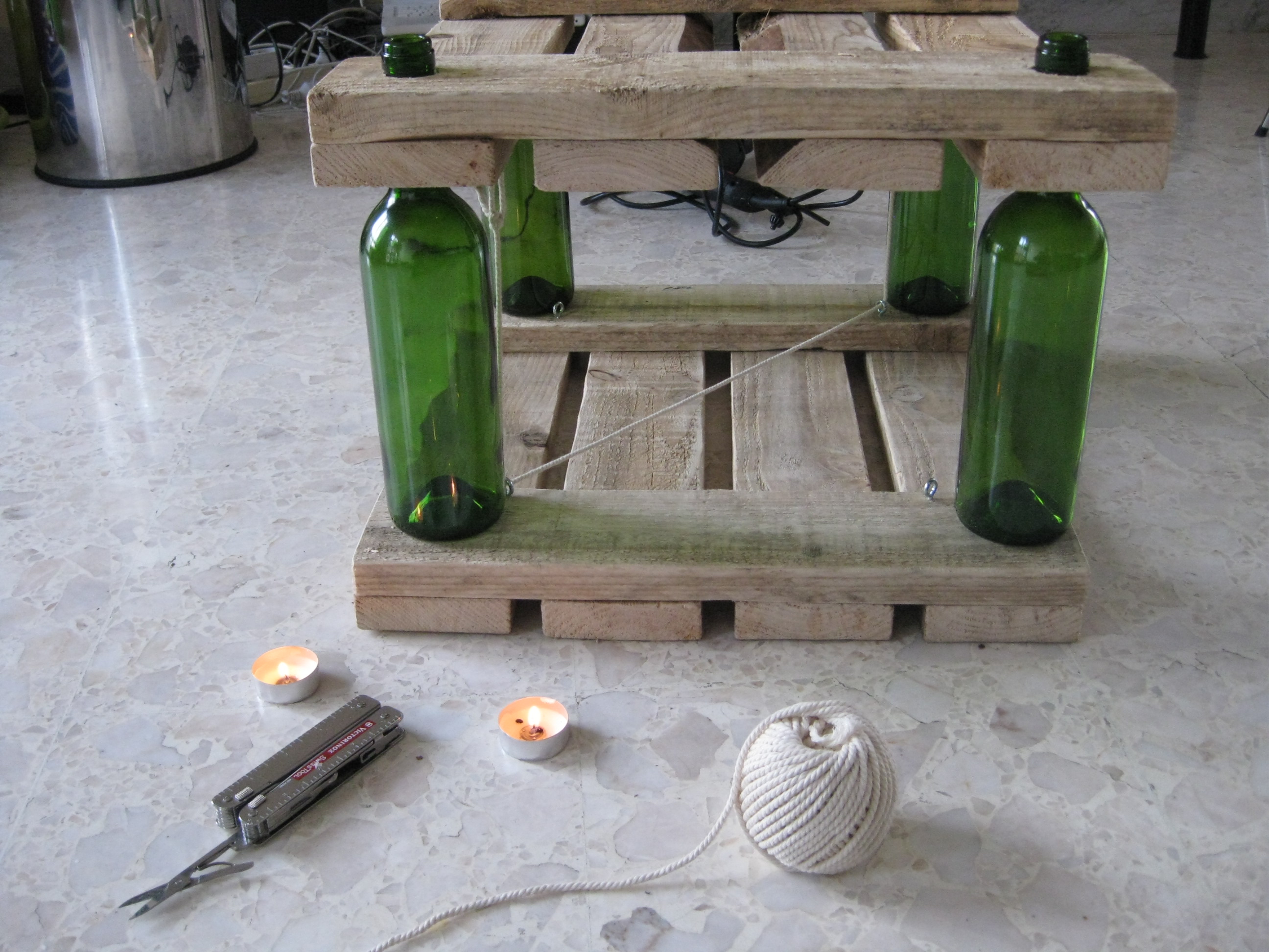
Half of the tensioning system in placeA detailed view of how the rope is kept under tension
With two levels done, I screwed eyes at the eight inside corners of the table, inserted the wine bottles and layed the table upside down to build the tensioning system. Starting from a bottom eye, I routed the string in the upper eye and then to the opposite corner and down again; Tied both ends and repeated for the other side. To prevent the ends of the strings from fraying, I dipped them in melted candle wax. Then, all there there was left to do was to put a long enough (to give torque) wood screw with an unthreaded shank between the two strings where they met in the middle of the table and turn to tighten the rope. Once I felt there was enough tension I simply drove the screw in the surface above to lock the whole system in place. Make sure the string is able to withstand a fair amount of tension because you need some if the bottles are to be kept tightly sandwiched between the two levels.
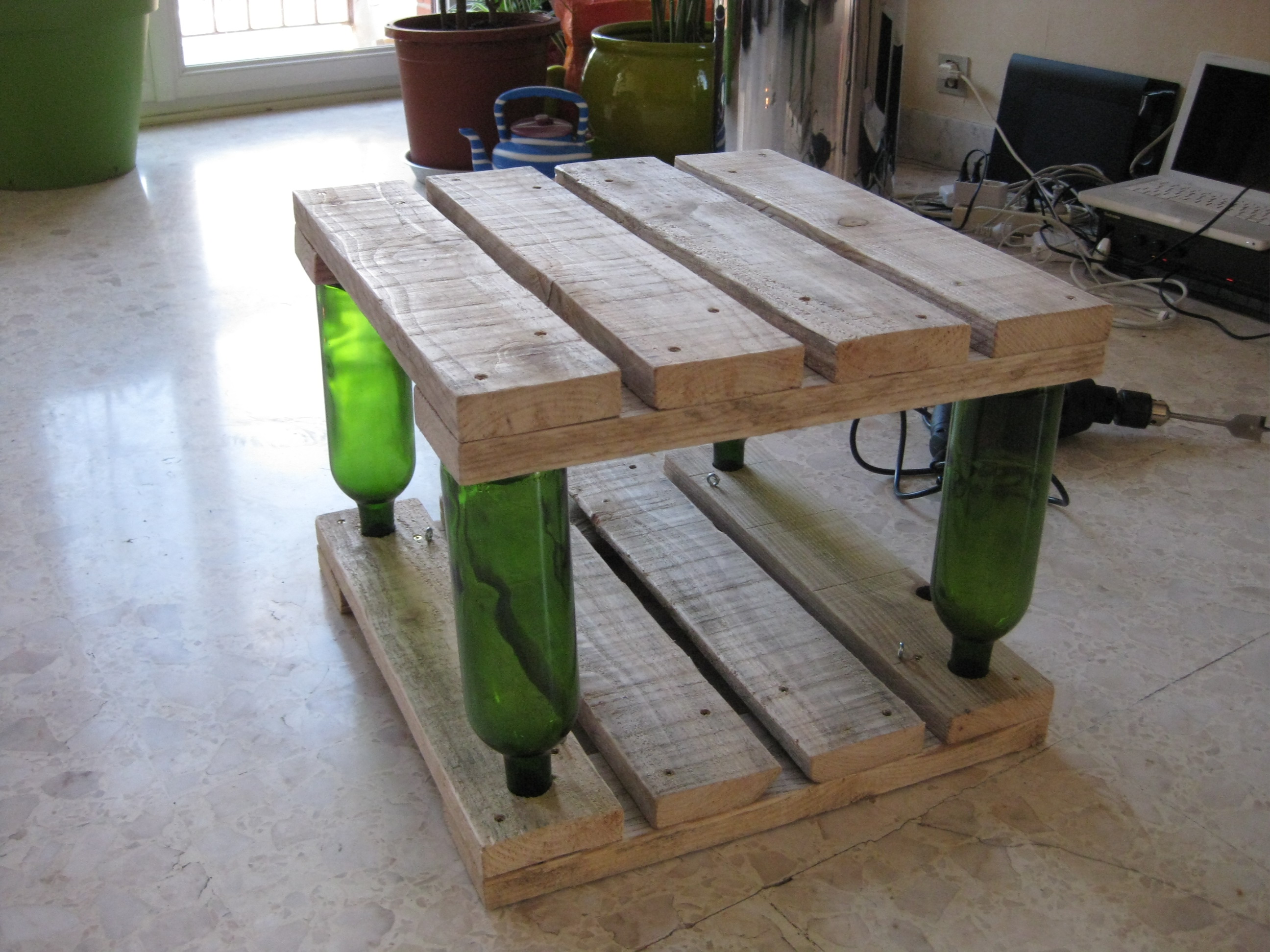
Assembling a two (or more) level table was a matter of simply repeating the process. The two level table ended up being more stable because the wood was just thick enough for the neck of the upper level bottles to lock itself inside the dip of the bottle below. The necks will make nice feet but If you want more adherence on the floor or want to protect it, you can put back corks into you bottles. Also, you are by no means limited to wine bottles, it could be beer bottles (on a good night with a few friends, you can get enough for a full shelving unit), or hard liquor bottles (but they take more time to accumulate in quantity).
The finished two level table
The coffee table
A detailed view of how the rope is kept under tension
The Joule thief is a really fascinating circuit, simple yet very intricate. Basically, it’s a step-up converted in its most elementary expression. I will spare you the theory since there is plenty of information on it on the web; rustybolt.info is a good place to start.
Joule thieves in all sorts of forms have been featured countless time on DIY websites and I felt it was time I build one. However, I did not want to leave the circuit at the breadboard stage because as it stands, the joule thief has characteristics that make it very attractive for all sorts of low power applications and I figured a flash light would be a very good home for a joule thief, where having the option of using dead batteries is certainly a big plus not to mention using less cells because the circuit steps the voltage up. Why dead batteries? Because a battery is never really dead, its voltage just falls down logarithmically until it hits a point where the device it was powering up stops functioning, which does not mean the battery is totally drained but rather that its voltage has fallen below a usable level. Since joule thieves are step-up converters, they can take that “dead” battery, and give it a new life by stepping up its output voltage to usable levels again.
The build
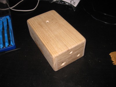
A 2 AA batteries Maglite
For my flashlight, I opted for a maglite body for its sturdiness and simplicity. I have been using those for years and they have served me well, but with traditional incandescent lamp bulbs (I do know they make LED versions now), they eat through batteries like crazy. So the challenge was to convert a 2 AA battery maglite so it could run off a joule thief circuit and a single AA but could easily get converted back to using a lamps(As I will tell later, the joule thief’s light output is not so strong … sufficient in most cases but not strong).
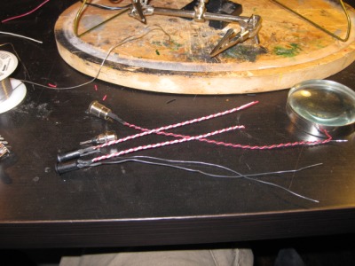
As I would be using one less battery, the trick was to use that space to hold the circuitry. I proceeded to cut a perfboard the size of an AA and soldered all the components on it with the heads from two nails as connectors. Inductors being already pretty hard to come around, one tailored to this application would be next to impossible to find so I had to hand wind one using 20 or so turns of 40 awg enameled wire (almost hair thin (also hard to find, look for it on ebay)) around a ferrite core to build the joule thief’s coil. Once everything was in place, I soldered the circuit ground wire, which when making contact with the flashlight’s body, would turn it on or off. That wire had to be routed inside the plastic insert that normally holds the lamp and its metal pad in place so that when you turn the head of the maglite, it screws up and presses the pad against the body, thus closing the circuit. In order to allow the maglite to be converted back to using a lamp, I just cut a notch under that pad so that pressure on it would contact the wire and ground it.
For protection and isolation, the circuit was wrapped it with acrylic tubing (some leftovers from the time my computer was watercooled) and inserted in the body. Finally, I installed the LED at the top, with its two pins bent to fit in the holes normally meant for the incandescent bulb. The lens fits perfectly on it; the only way to tell it’s a modified maglite is to look at the bulb.
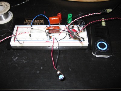
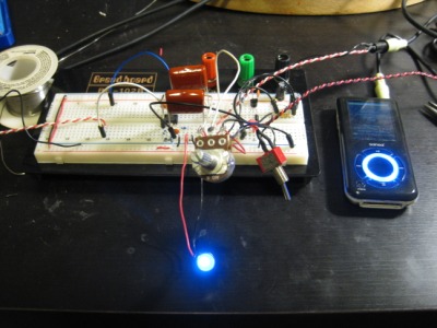
The circuit being constructed.Testing the circuit.A correctly working joule thief.The finished circuit in its protectective acrylic tubing.It works!
Results
I will right away admit that I am a bit dissapointed with the light output of the circuit. Though I did expect it to be a whole lot less than the incandescent bulb, it is barely usable. The culprit is certainly the LED. At only 3mm, it can only do so much with that waveform going through it ; it’s rated for 20mA and its getting 12 so the circuit is doing a correct job keeping in mind that joule thieves are quite inefficient ( in the order of 30-40% judging by the duty cycle). Using a larger inductance is out of question because it reduces the frequency without modifying the waveform but using a larger wire gauge (thus lowering the resistance of the coil, see below) would probably help. What also does appear to make a difference is the type of transistor used, I noticed that the current draw of the LED was only 9mA with a 2N3904 while it jumped to 12 with a PN2222A. Both are general purpose NPN so maybe another type of transitor would do better. As a side note, the circuit will not work with FETs, I have found plans to build a joule thief with those but its much more complicated.
With a single battery at 1.435V, I got two days of continuous lighting, not bad. At that voltage, the current draw is about 65mA. I was not able to measure the pull of the standard incadescent bulb for comparison because the inline resistance of my multimeter was too consequent, but one interesting thing I noticed was that below a certain voltage, the light would start to flicker at hertz or so. Its hard to see in the picture, but I added an electrolytic capacitor for bypass; it could have something to do with that.
Even though I said that the light output was nothing to brag about, I did take the flashlights to many trips in the woods, with some lasting a few days and it has held up perfectly. With your eyesight accustomed to the dark a bit, you can see at a few meters and whatever task your hands are doing is lit well enough for comfort. With all this serious usage, I have not yet ran out that dead battery. Too bad, I wish I could have gone out asking my hiking buddies for dead batteries.
With LED flashlights being quite effective, I can’t vouch for the potential of this circuit for such applications. Certainly, using dead batteries is a plus as they are relatively easy to come by, but the low light output would certainly be a killer for most of us because when it comes to photons during a moonless night in the woods, more is just better.
According to rustybolt (thanks), my coil is mainly to blame for my poor performing Joule thief. The wire used is too thin and has a consequence opposes too great of a resistance ( I should have tought about that) to the current, thereby limiting the LED’s brightness. There is a very clear article on Joule Thief coil selection on his site. He also points to the transistor being responsible for the loss of efficiency. Next time I get my hand on that maglite (I’m travelling right now so it’s an ocean apart from me), I’ll revisit the circuit.
Too bad I work alone and mostly at nighttime. Otherwise, I would have some people around to share the sheer joy that I am experiencing right now. For a lack of that, I’ll turn to the web. Just an hour ago, I completed a major milestone in my main project line. I am ecstatic as with work of this magnitude, the light at the end of the tunnel is always months away( and right after, you get into another tunnel…) Here is the writeup on the situation.
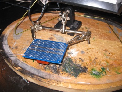
I have had a fascination with oscilloscopes for a very long time. While being incredibly useful (for those who are into electronics that is), they have a mysterious sense to them that still gets me after all those years of hanging out with complicated machinery. I remember clearly seeing rows and rows of them during my first university year, having only a very rough idea of what they were for but still knowing, judging by their numbers, that they must be very useful for every electronics bench to get its own. They are what epitomizes the knobs and dials (screen in this case) strange and obscure apparatus of the modern age.
So much so that I decided to program one from scratch for my final engineering project; I had very ambitious plans for it. The electronics would be managed by a Microchip PIC18F4550 – a USB microcontroller – and the application on the host PC would be programmed in C#. Its killer feature would be that its display would be 3D, giving the user one more dimension for visualizing, combining and probing waveforms. Turned out implementing the USB stack was a major bitch (should have used Microchip’s ready-made one…) so I decided to get signals through the sound card input. No big deal, the main application was agnostic as to where its data came from. Then, the 3D part was a huge headache too (80% of the code, a primitive but complete 3D engine), but I got trough it and in the end it worked well enough for a public showing. I will post all its code and some screen shots when I find the motivation too, but for reasons that will be developed upon at this time, I decided no to further its development. Simply put, I had discovered the world of Open Source and realized that platform-locking my project (DirectX, .NET) was not inline with my philosophy of getting good electronic tools in the hand of the masses.
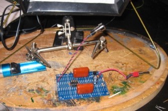
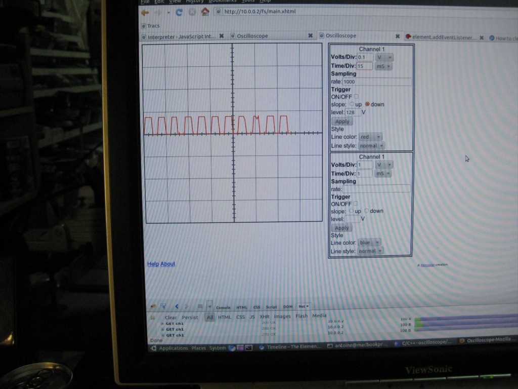
This new one is implemented on an OS of mine (Elements, but beware, the post is very outdated) and thus completely web oriented and RESTful. The user interface is described in XHTML, SVG and JavaScript with all of it getting served along with the oscilloscope function by an ATMega328p with 32kB of static EEPROM storage. That’s a web server, TCP/IP stack, a file system and oscilloscope running on 32kB of Flash, 32kB of EEPROM and 2kB of RAM embarked on a 16 MHz chip! It had been a web server for quite a while, but tonight, I got it to behave like a usable oscilloscope. I am a happy man…
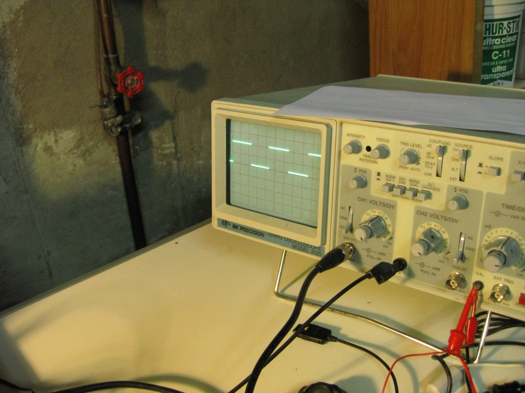
Close up of the standard oscilloscope’s screen.
Closeup of the Firefox screen. What a stupid way to take a screenshot…
A comparison the standard oscilloscope’s calibration waveform displayed on itself and using my project on Firefox.
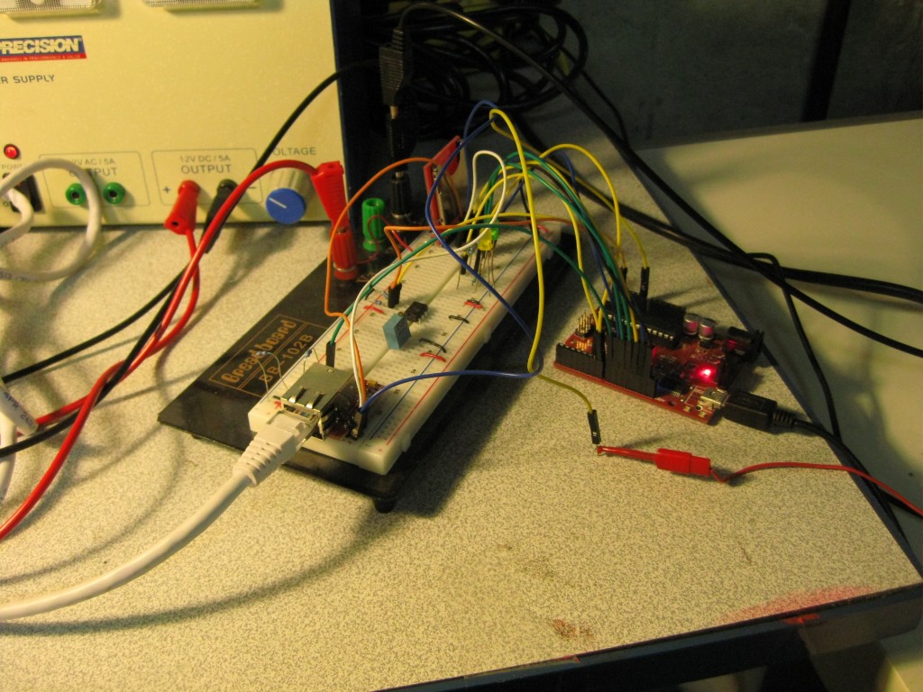
The electronics on a bread board. You can spot and Arduino clone (Freeduino SB), the EEPROM, the Ethernet interface (an ENC28J60) and an SD card slot (not in use, FAT16 and SD/MMC was to demanding on flash and RAM space)
One of my friends, who creates music as a hobby, recently bought a pair of AKG 601 headphones. While I do listen to a fair amount of music, I would not consider myself an audiophile or anything close to that. However, those headphones do make a difference I can notice in the quality (or lack thereof for low bit rate MP3s) of whatever is being played. There is only one small problem with them. Being massive open headphones, my friend’s sound card is only able to put out an acceptable level of sound at maximum volume; his MP3 player, on the other hand, is simply incapable of driving them. The AKG 601 have a rated impedance of 120 Ohms while normal earbuds seem to be around 20. As a result of a soundcard’s output impedance being too high, a normal speaker output is not capable of providing enough current to the headphones.
They are huge, expensive and leak a lot of sound, so he does not plan to use them on bus rides, but there are still some serious downsides with having to drive them at maximum volume:
Levels of distortion increase significantly as maximum power is reached in an amplifier. This means that running the volume at maximum produces sound of a lower quality than if it was outputted at 50% and then passed trough a more capable amplifier.
When he creates music and wants to listen to specific instruments or tracks that are not as loud as the rest he is stuck with the current level of volume.
To address those problems he was considering purchasing a headphone amplifier, but to me, this seemed like the perfect opportunity for a diy solution. As he is not at all familiar with the world of electronics, I offered myself for the task as it was a good and easy way to get my hands dirty with pure analog stuff and get acquainted with audio. My background is more software with the occasional digital circuit. I did learn about all the concepts in application in this project at school, but the retention capacity of my brain decreases significantly when the interest is not there, and a bunch of formulas splattered on a white board does not tell me how to use an op amp in real life.
Since parts are cheap and shipping isn’t, I decided to build one for me as well. This post details the process but its not a how-to for the CMoy as there are alrealy a ton around the web.
Circuit
I started my research on the excellent diyaudioprojects.com and found the CMoy/Grado RA-1 project. The circuit looked simple enough and according to the author, the quality was on par with a Grado RA-1 which retails at 425 $US on amazon. It turns out that the CMoy pocket amplifier, named after Chu Moy, its inventor, is a very popular design. You can find kits for it on the web that are about an order of magnitude cheaper than the RA-1 it aims at emulating.
Amplifier circuit
Chu Moy’s website provides a wealth of information, but the one that help me the most by far was Warren Young‘s tutorial on the CMoy.
Do not let yourself be fooled by the simplicity of this circuit, there is a lot more to it than meets the eye and tangentsoft’s tutorial does an outstanding job at explaining all the specificities and what you need to be concerned about when making modification. It took me about ten minutes to get a working version on a breadboard, but actually understanding it required a fair amount of reading and thinking. Once again, Warren’s site proved ato be invaluable resource in this, especially his audiologica section. Some amplifier designs on his website are considerably more complex than this one and would be a nice progression from this project.
Power supply circuit
The power supply is no too complicated but somewhat unconventional because of its use of a virtual ground, something that was previously unknown to me. My design is generally the same except for the addition of a linear regulator and a protection diode as I did not want to run it from a 9V battery and the wall wart I had lying around was unregulated. For the amplifying part, I added a resistance in parallel with the volume pot to make it behave in a more linear fashion (I bought a log one), some decoupling ceramic caps for the op-amp’s supply lines and upped the value of C1 from 0.1uF to 1uF to let trough lower bass frequencies. Every CMoy amplifier circuit variation uses different resistance value. R2 is fairly constant at 100kOhm as it forms toghether with C1 a high-pass filter. R3 and R4 will vary depending on the gain required. The power supply part is pretty straightforward but you will need to find a value for R2 and R3 that will strike a good balance between not draining the battery too fast (should you choose to go that route) and providing the virtual ground enough current sink capability.
Power consumption is very low. I am using a 9V unregulated wall-wart with a current rating of 100mA. Since the amp cannot load it fully, the output voltage at the connector is around 12V which leaves plenty of room for subsequent regulation down to 9.5V. The linear regulator is an absolute necessity as its omission lets trough a very audible hum.
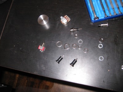
While this circuit will work with any standard parts (which I used for the prototype), it is best to use audio grade components. This is often synonym of overpriced, but in this case, since we are talking small and simple, you can get away with only investing a few more dollars. For the op-amp, I selected the Burr Brown OPA2134 as recommended by CMoy and decided to go with polypropylene metal film capacitors instead of polyester. I also got a gold-plated IC sockets and audio jacks. The only non-standard part was the volume pot, which had to be dual-gang in order to control both channel at once.
Prototype
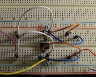
Protype with generic components
Naturally, everything stated on a bread board. There is nothing spectacular about that, but when I first put toghether the circuit, all I had to work with was some general purpose op-amps (MC1458) and some electrolytic caps. I was unsure whether the op-amp would be sufficient or not, but I did know electrolytic caps are only to be used in a bypass configuration as they induce a fair amount of distortion when used in line. Regardless, there was improvement in comparision with not using an amp at all. At this point, I became confident this would not be another useless circuit and things could only get better with the “audio grade” parts.
Prototype with audio-grade components
When I received the components I ordered from mouser specifically for this project, I instantly swapped them on the protoype and was rewared with a increase in quality… or so I think. The term “subjective” applies especially well to the audio realm; due to known psychological effects, me knowing the components were actually better in theory rendered me incapable of judging whether there was an improvement or not. Then again, I do not really know what to look for but I would consider the overall difference to be subtle enough to be affected by skewed perception. This is why I decided to take my friend trough some blind tests. He does not know a capacitor from a resistance and much less their potential effect on sound, on the other hand, he know music and most likely has a more discerning hear than mine; he is the perfect candidate. More on that at the end of the post.
Enclosure
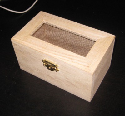
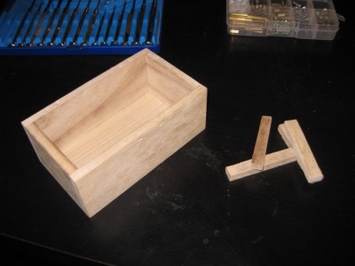
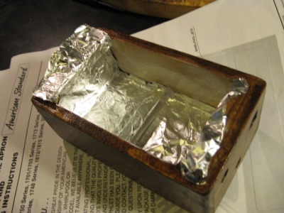
The original box
While the parts were on their way, I decided to get started on the enclosure right away. Naturally, I would have gone towards a plastic project box but while me and my friend were discussing the project, he suggested the use of a small wooden chest as he had one handy and felt a tupperware container would not do a piece of quality audio equipment any justice. Upon inspecting it, I figured it would be pretty easy to turn it into something visually pleasing with a bit of woodworking. I found my box at Michael’s for $3.50. I had never worked on wood (except while renovating but I would not consider this woodworking) so I was somewhat unsure of the end-result. With perspective, this is the prettiest project enclosure I have built so far and for that price, I’ll definetly repeat this design.
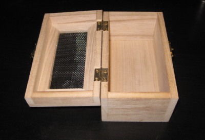
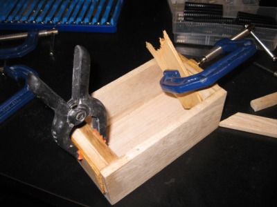
The box went trough several modifications. First, the lid was removed and disassembled. The rectangular pieces of which the sides of the lid were made were cut and glued to the box. Two there added to the opening of the box to provide a bit more support for feets while the two others where glued to the bottom to raise the pcb.
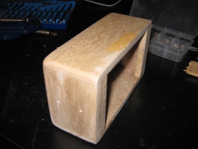
The holes and marks where the hinges and lock used to be were filled with wood filler and then the edges were sanded down to give the box a rounder shape. Lastly, holes to accomodate the various connectors and holders were carefully (pine is very soft and chips easily) drilled.
Since the box was made out of pine, it needed to have wood conditionner applied on it. It took me a while to figure out how to use this product as information from some diy sites conflicts with the manufacturer’s label and everyone seems to have their particular process when it comes to preparing soft wood for staining. I finally came across a site that explained that wood conditionner was actually diluted varnish. Consequently, it needed a day of drying to properly seal the wood’s pores and allow even stain penetration. This contradicted the can’s label which directed to apply the stain within two hours of applying the conditionner. I ended up following the website’s advice and let it dry overnight. The stain came out beautiful and uniform without any blotching while tests using the manufacturer’s instructions on scraps where not so conclusive.
After staining, I applied two coats of polyurethane warnish with some light sanding in between and that was it for the box. It took three days including drying time but overall, I would estimate the amount of time invested to two hours with sanding being the longer task.
Soldering
Soldering the circuit was somewhat harder than usual because of the PCB I used but with any
Circuit in fabrication
standard board this should be an easy task. The routing is straighforward but ideally, everything affecting the signal path should be kept as close as possible so as to avoid the side effects of long wires (inductance, capacitance, EMI pickup). Mine required a fairly sized board because of the polypropylene capacitors, but with small components, everything should fit on two postage stamps and not take more than two hours to solder.
Finalization
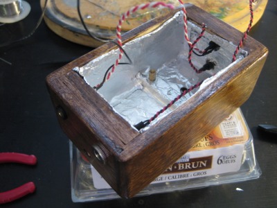
To block any unwanted EMI, I lined the inside of the box with two layers of aluminium foil glued toghether like Mark did on his CMoy/Grado RA-1 project. Whether this is useless or not I cannot tell, but it certainly cannot hurt. I still have some old CRTs at my parent’s place so when I get the chance, I will try and see if it picks up anything.
Fitting everything inside the box.
Installing the circuit in the box is no simple task as all the connections have to be soldered while it is in there sitting in mid air. Incidently debugging also has to happen in this position. Mine did pass the smoke test but it did not work correctly the first time around. It turns out I had soldered one channel of the pot the wrong way.
Sound
As mentioned in the intro, I would not consider myself versed in the art of listening and I much less have the capacity to describe sound with words. However, I can certainly tell it makes a noticeable difference in quality of the music. Even with my old and battered Koss headphones it sounds better but when I got to try it with my friend’s AKG-601 I was blown away and felt for a minute I should make the investment and get myself a pair.
The downside of better sound is more obvious compression artifacts; a good amplifier will not discriminate either. Some of my tunes which sounded fine on my MP3 player with earbuds are now barely listenable because of the effectiveness of the amp at reproducing what it takes as input. I finally got a around to finding a few MP3 in my collection which were of good quality, but you should nonetheless be aware that if the end product sounds bad, check the MP3s first before probing the circuit for a problem that isn’t there.
I have only listened to it for a few hours so far and apparently, it get’s better with time as parts burn-in (like engines??). This seems odd to me, but I will take the web’s word on that. I could somehow see this phenomenon coming into play with tubes and high-powered solid-state amplifiers as they are genereally under a lot of thermal stress but for this little mW scale headphone amp, I have my doubts.
(Scientific) Test
Yes, it does sound better, but that’s only my opinion. And a very biaised one because I researched and built the whole thing and incidently, would be very disapointed if all that work did not pay off. It certainly feels like adding the amp to my listening set-up improves the sound, but you can only live with a placebo effect for so long, so I got two friends including the one for which this project was started in the first place and did a blind test.
There were initially four configurations but we decided to drop one for fear of not completing the test before the beer store closed:
Straight MP3 player
MP3 player and prototype circuit (no audio-grade components)
MP3 player and finished amp
The headphones were obviously the same for all tests and the volumes were adjusted to approximatively the same level. The MP3 player when used alone had to be set to its max volume which is a good thing since the whole purpose of the headphone amp is to avoid this as it dramatically increases the distortion level.
A run would consist of 1 minute of listening to the same song (Californiacation by Red Hot Chili Pepers; everyone I know likes this song) on every configuration. The subjects did not know which one it configuration they were listening with, all they could see was me shuffling wires behind a box and then handing them the headphones. We repeated the run three times so as to increase the chances of getting a statistical significance.
One subject got discouraged in the middle of test, complaining that it all sounded the same to him but despite his lack of faith and to his amazement, the results confirmed the predictions. In order of quality:
Prototype
Finished amp
MP3
The rating scheme was a sort in order of preference, but one decided to rate using half marks so the results group the two amps closer toghether. The MP3 player was identified as worst every time while the two amps shared the top two almost equally. I would have expected the finished amp to come out first but after some careful listening to the actual track, I realised compression artifacts were more audible on it. This is probably due to the OPA2134’s better bandwith as artifacts are generally found in higher frequencies. The MP3 player just by itself did sound truly awful, Some artifacts were not present while others were exacerbated but overall, it felt a bit like listening to the FM radio.
Conclusion
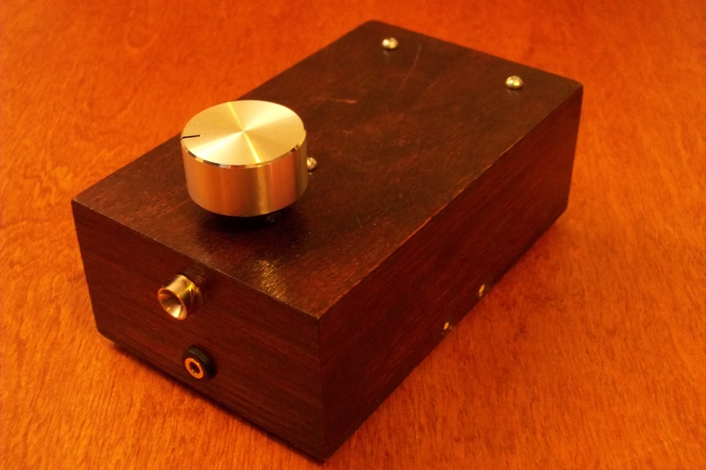
Front
Simple, quick and inexpensive projects are definatly a rare occurance in my life, so this one was definetly a welcomed breath of fresh air; its nice to finish something and it gave me a break from battling with C++. It is not perfect yet but when I get the motivation, I’ll get to correcting the small bugs: mainly a minute discrepancy between the left and right gain (resistor/pot variation) and a not linear enough pot. For the time being I’ll just enjoy it as is.
Back
Building audio equipments is definelty something I will revisit in the future. It’s a break from routine and a very gentle way to get familiarised with the mysterious and unpredictable field of analog electronics: everything works at a low frequency and a low votlage so you can be confident nothing extra weird is happening. As a plus, you get something useful at the end of the day. To summarize, this project is the perfect “Hello world” equivalent.
Next step will be a full scale amp with some digital controls; the circuit is putting itself toghether in my mind as I write those lines, but it will have to wait for a while as I have other stuff that needs to get finished and still in the process of salvaging components.
My friend’s version
My friend's CMoy amp
Not that different actually, but it took a while before we could meet (with 500 km separating us) and sit down for a few hours (from 20:00 to 04:00) to finish the project. I had given him a plan and a solder iron, but we ended up completing the project together. In retrospective, there was no way he could have worked on the thing like I hope he would; I even had soldered the voltage regulator backwards and besides that, there we a massive amount of obstacles I strongly doubt someone with no electronic background could have overcome. Still, it was fun getting high on solder fumes along with him. Tests were conclusive and he is now the proud owner of a clone of a 425$-ish amp clone. The one thing we changed was how the volume pot behaves. I had originally bought a log version but found out it was only useful at 80% of its range so I added a couple resistors to make my friends’s pot behave a bit in a more linear fashion.


")